Download
1 / 20
200 likes | 224 Vues
Explore the characteristics of port fuel injection systems, injector matching with engine requirements, electronic fuel injector actuation, and spray quality. Learn about injection pulse duration, control of mass flow, and EFI tuning.

E N D
Flow Characteristics of Port Fuel Injection System P M V Subbarao Professor Mechanical Engineering Department Matching of Injector with Engine Requirements
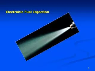
Electrical Input to Control Injector Operation An injector is essentially a gate valve for fuel delivery. Increasing fuel pressure can allow to cram more fuel into the intake port for a given injector pulse width. Injection Pulse Full Open Accelerator Once in two Revolutions Idling Cold Starting
Flow Characteristics of Injector - 2 Throttle Body Injector 7.0 gms/s Port Injector 3.5 gms/s
Spray Quality: Representative Mean Diameter German scientist J. Sauter : 1920 • Introducing the definition of SMD: Empirical Formula for prediction of possible SMD: where dnozzis the nozzle diameter, μf , μg are the fuel and gas dynamic viscosity, respectively, Re the Reynolds number and We the Weber number.
Injection Pulse • The length of time an injector is open and squirting fuel is called the "pulse width," and it is measured in milliseconds (ms). • At a given rpm, an injector can only be held open for so long before it needs to be held open again for the next engine revolution -- this is called its "duty cycle."
Selection of Injector Driving Pulse Duration • Considering a specific injection end time, the increase in injection pressure has below results: 1. Increasing vaporization rate in case of relative velocity increase of fuel injection. 2. Reduction in droplets means diameter and increase of droplets surface contact that makes much vaporization rate. 3. Increasing the spray cone angle that provides wither spray angle and much fuel wetted surface in the intake port. 4. Reducing the in hand time for fuel vaporization in the port and cylinder because of thinner injection pulse width.
Control of Mass Flow Through an EFI • The mass flow through an EFI is selected based on three main factors. • Engine rpm, • Throttle position, and • Oxygen remaining within the exhaust. • The distributor triggering contacts relay the engine speed to the Electronic Control Unit (ECU). • The load on the engine is taken from the intake air pressure sensor. • These factors influence how long the injectors remain on for.
Exclusive Operations of EFI : Special Tunes • When the engine is first started, the starter is on; additional gasoline is pumped through the intake manifold. • When the car is accelerating, throttle position is closer to wide open, the amount of time the injectors remain on is longer. • When decelerating the fuel injectors remain turned off until the rpm’s drop below 1,000, when the injectors open again to allow the engine to run in the idle mode.
A square wave is used to drive the electronic control unit. The square wave is either on or off, 1 or 0. The major concern is to reduce the lag between when the electric pulse is received and when the solenoid is discharged. By increasing the pressure of the fuel coming into the injector and reducing the air gap you can accomplish this goal of reducing lag. Time Constant of Injector • The air gap is based on the distance between the needle of the fuel injector when it’s fully closed compared to when it’s fully open. • The more pressure you have the less time it takes for the correct amount of fuel to be distributed and also reduces the size of the hole needed to allow the fuel into the manifold.
Injection Pulse • The length of time an injector is open and squirting fuel is called the "pulse width," and it is measured in milliseconds (MS). • As rpm increase, an injector can only be held open for so long before it needs to be held open again for the next engine revolution -- this is called its "duty cycle." • Even though a fuel injector's flow rate is measured at its maximum duty cycle (100%), fuel injectors should never be operated at 100% duty cycle. • Instead, a typical maximum duty cycle is around 80%. • Fuel pressure plays a big role in the operation of a fuel injection system. • Because the injector is essentially a gate valve for fuel delivery, increasing fuel pressure can allow you to cram more fuel into the intake tract for a given injector pulse width.
Speed Density Electronic MPFI • Speed-density system uses engine speed, manifold pressure and air temperature to calculate the engine air flow. • The electrically driven fuel pump delivers the fuel through a filter to the fuel line. • A pressure regulator maintains the pressure in the line at a fixed value (270 kPa). • Branch line leads to each injector, the excess fuel returns to the tank vial a second line. • Typical injection times for automobile applications range from 1.5 to 10 ms. • The appropriate coil excitation pulse duration or width is set by the electronic control unit (ECU). • In speed-density system the primary inputs to the ECU are the outputs from the manifold pressure sensor, the engine speed sensor and temperature sensors installed in intake manifold.
For warm-engine operation, the mass of air per cylinder per cycle is: • The ECU forms the pulse which excites the injector solenoids proportional to estimated mass of air. • Addition temperature signals are used to find out cold start or hot engine cylinder conditions.