Download
1 / 76
760 likes | 795 Vues
Explore 4 alternative design concepts for an Instructional Lab Facility by the Mountain Ridge Project team in the conceptual development phase. The project includes various office spaces, classrooms, labs, and more across 3 floors. Each alternative offers unique features and structural elements to enhance functionality and aesthetics.

E N D
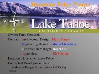
Mountain Ridge Project • Owner: Tomo Cerovsek • Contract: Architectural Design: Mario Sargac Engineering Design: Michael Jewsbury Construction Manager: Roger Lee Apprentice: Kit Fleming • Location: Hope River, Lake Tahoe • Conceptual Development Phase • 4 Alternate Designs for Instructional Lab Facility
Ridge Team ~ Architectural
Alternative #1 • Faculty offices • Chair’s office • Senior Admin. office • Secretaries • Faculty Lounge • Student offices • Auditorium • Faculty offices • Chair’s office • Senior Admin. office • Secretaries • Faculty Lounge • Student offices • Auditorium • Faculty offices • Chair’s office • Senior Admin. office • Secretaries • Faculty Lounge • Student offices • Auditorium • Large classrooms • Small classrooms • Seminar rooms • Instructional labs • computer machine room • Technical support • Storage • Large classrooms • Small classrooms • Seminar rooms • Instructional labs • computer machine room • Technical support • Storage • Large classrooms • Small classrooms • Seminar rooms • Instructional labs • computer machine room • Technical support • Storage 1st floor plan 2nd floor plan 3rd floor plan
Alternative #1 • entrance from Ridge View Rd
Alternative #1 • gaining natural light
Alternative #1 • fractionized structure
Alternative #2 • room layout • affinity / rejection • extra security
Alternative #2 • Faculty offices • Chair’s office • Senior Admin. office • Secretaries • Faculty Lounge • Student offices • Auditorium • Faculty offices • Chair’s office • Senior Admin. office • Secretaries • Faculty Lounge • Student offices • Auditorium • Faculty offices • Chair’s office • Senior Admin. office • Secretaries • Faculty Lounge • Student offices • Auditorium • Large classrooms • Small classrooms • Seminar rooms • Insrtuctional labs • computer machine room • Technical support • Storage • Large classrooms • Small classrooms • Seminar rooms • Insrtuctional labs • computer machine room • Technical support • Storage • Large classrooms • Small classrooms • Seminar rooms • Insrtuctional labs • computer machine room • Technical support • Storage 1st floor plan 2nd floor plan 3rd floor plan • 2 entrances from N • room layout • 2nd geometry • challenging cantilever
Alternative #2 • entrance from Ridge View Rd
Alternative #2 • mountain & river view
Alternative #3 • Faculty offices • Chair’s office • Senior Admin. office • Secretaries • Faculty Lounge • Student offices • Auditorium • Faculty offices • Chair’s office • Senior Admin. office • Secretaries • Faculty Lounge • Student offices • Auditorium • Faculty offices • Chair’s office • Senior Admin. office • Secretaries • Faculty Lounge • Student offices • Auditorium • Large classrooms • Small classrooms • Seminar rooms • Instructional labs • computer machine room • Technical support • Storage • Large classrooms • Small classrooms • Seminar rooms • Instructional labs • computer machine room • Technical support • Storage • Large classrooms • Small classrooms • Seminar rooms • Instructional labs • computer machine room • Technical support • Storage 2nd floor plan 3rd floor plan 1st floor plan
Alternative #3 entrance Ridge View road • AutoCAD 3D model
Alternative #3 two grids utilizing two grids • two grids / two options • exterior / interior grid
Alternative #3 extra columns • proposal of extra columns • combined grid combining two grids
Alternative #3 • NetMeeting session
Alternative #4 • Faculty offices • Chair’s office • Senior Admin. office • Secretaries • Faculty Lounge • Student offices • Auditorium • Faculty offices • Chair’s office • Senior Admin. office • Secretaries • Faculty Lounge • Student offices • Auditorium • Faculty offices • Chair’s office • Senior Admin. office • Secretaries • Faculty Lounge • Student offices • Auditorium • Large classrooms • Small classrooms • Seminar rooms • Insrtuctional labs • computer machine room • Technical support • Storage • Large classrooms • Small classrooms • Seminar rooms • Insrtuctional labs • computer machine room • Technical support • Storage • Large classrooms • Small classrooms • Seminar rooms • Insrtuctional labs • computer machine room • Techincal support • Srorage 3rd floor plan 1st floor plan 2nd floor plan • soft fluid among stones
Alternative #4 • sense of gravity
Alternative #4 • entrance from Ridge View Rd
Alternative #4 • growing structure
Alternative #4 • building as balancing item
INTRODUCTION • Structural Scope • Design Parameters • Gravity Framing • Seismic Framing • Four Alternatives • Material Selection • Systems • MEP
Alternate 1 Added Shear Wall
Alternate 2 Added Bracing Tower
Alternate 3 Added Support
Seismic Framing for Each Alt. • Determine the magnitude of seismic forces • Design of Steel/Concrete/Composite diaphragm • Conceptualization of Lateral Force Resisting Elements • Details, Details, Details
Diaphragm • Distributes shear forces to LFRs • Static analysis showed maximum stresses to be 200 psi Maximum • Metal deck-PCC composite on 2nd,3rd,and Roof • Steel deck spans @ 10’ between beams “one-way” • Portland cement concrete via pump-truck • Wire mesh reinforcement and chord steel Shear Stud Reinforcement Steel Deck Concrete
Overturning forces are not significant • LFR Systems • Steel • Chevron Bracing • Moment Frames • Concrete • Ductile Shear Walls • Moment Frame • Precast • Ductile Shear Walls • Post Tensioned Moment Frame
Seismic Framing: CBF WT18x65 2L6x6x1/2 Shear Deformation
Special PT Moment Resisting Frame Precast Sections: Moment Frame allowable in building code with special testing Construction Problems, Ductile and Safe, Allows long, open, uninterrupted spans PT Moment Frame
Structural: Seismic Framing Shear Wall • Cast-in-Place • Simple • Ductility depends on failure mechanism • Requires Architectural Space
Typical Connection Details Worst Case Steel Connections
Typical Connection Details Column Foundation Column Beam Confinement
Foundation System • Function of our foundation system • Handle vertical loads • Resist lateral forces • Site Profile • Bedrock • Very high bearing capacity • Very low settlements • Shallow Foundation • Bearing pressures 5 kips/sq.ft. • 4’x4’ Footings under columns • 12”-18” strip footing (Perimeter and LFRs)