
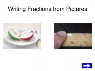
Advanced 3D Reconstruction from Image Collections: Camera Calibration and Structure Estimation
This work delves into computing 3D structure and camera parameters from a collection of images, a significant achievement in 1990s computer vision. The process entails estimating camera poses and sparse scene structures using direct linear transformations and minimizing geometric errors through iterative optimization. We explore the relationships between image pixels and rays in space, detailing camera calibration techniques, the fundamental matrix, and automatic correspondence finding via feature detection. This presentation includes critical algorithms and applications for enhancing 3D scene reconstruction.


Advanced 3D Reconstruction from Image Collections: Camera Calibration and Structure Estimation
E N D
Presentation Transcript
3D from Pictures Jiajun Zhu Sept.29 2006 University of Virginia
One of the most important / exciting results in computer vision from 90s’ It is difficult, largely due to numerical computation in practice.
But this is SO powerful!!!2 SIGGRAPH papers with several sketches this year!show a few demo videos
Now let’s see how this works! Input: (1) A collection of pictures.Output: (1) camera parameters (2) sparse 3D scene structure
Consider 1 camera first What’s the relation between pixels and rays in space?
Simplified projective camera model P P is a 3x4 Matrix 7 degree of freedom: 1 from focal length 3 from rotation 3 from translation x = P X = K [ R | t ] X
Consider 1 camera x = P X P3x4 has 7 degrees of freedom # unknown = 7 Each X gives 2 equations Given one image, we observe x 2n >= 7 i.e. n >= 4 Can we recover X or P? If P is known, what do we know about X? If X is known, can we recover P?
This is a Camera Calibration Problem Input:n>4 world to image point correspondences {Xi xi}Output:camera parameters P = K[R|T]
0 -w y w 0 –x -y x 0 where [Xi]x = Direct Linear Transform (DLT)
Direct Linear Transform (DLT) n 4 points minimizesubjecttoconstraint use SVD p is the last column vector of V: p = Vn
~ ~ ~ Implementation in Practice • Objective • Given n≥4, 3D to 2D point correspondences {Xi↔xi’}, determine P • Algorithm • Linear solution: • Normalization: • DLT • Minimization of geometric error: Iteratively optimization (Levenberg-Marquardt): • Denormalization:
~ ~ Camera centre C is the point for which PC = 0 i.e. the right null vector of P ~ ~ P = K[R|t] = K[R|-RC] = KR[I|-C] ~ write M = KR, then P = M[I|- C] How to recover K, R and t from P? Objective Given camera projection matrix P, decompose P = K[R|t] Algorithm Perform RQ decomposition of M, so that K is the upper-triangular matrix and R is orthonormal matrix.
Let’s consider 2 cameras • Correspondence geometry: Given an image point x in the first image, how does this constrain the position of the corresponding point x’ in the second image? • (ii) Camera geometry (motion): Given a set of corresponding image points {xi ↔x’i}, i=1,…,n, what are the cameras P and P’ for the two views?
Correspondence geometry: Given an image point x in the first image, how does this constrain the position of the corresponding point x’ in the second image?
The Fundamental Matrix F x’T Fx = 0
What does Fundamental Matrix F tell us? Fundamental matrix F relates corresponding pixels x’T Fx = 0 If the intrinsic parameter (i.e. focal length in our camera model) of both cameras are known, as K and K’. Then we can derive (not here) that: K’TFK = t cross product R t and R are translation and rotation for the 2nd camera i.e. P = [I|0] and P’ = [R|t]
Good thing is that … Fundamental matrix F can be computed: x’T Fx = 0 from a set of pixel correspondences: {x’ x}
Compute F from correspondence: separate known from unknown (data) (unknowns) (linear) How many correspondences do we need?
What can we do now? (1) Given F,K and K’, we can estimate the relative translation and rotation for two cameras: P = [I | 0] and P’ = [R | t] (2) Given 8 correspondences: {x’ x}, we can compute F • Given K and K’, and 8 correspondences {x’ x}, • we can compute: P = [I | 0] and P’ = [R | t]
This answers the 2nd question • Correspondence geometry: Given an image point x in the first image, how does this constrain the position of the corresponding point x’ in the second image? • (ii) Camera geometry (motion): Given a set of corresponding image points {xi ↔x’i}, i=1,…,n, what are the cameras P and P’ for the two views?
But how to make this automatic? • Given K and K’, and 8 correspondences {x’ x}, • we can compute: P = [I | 0] and P’ = [R | t] (1) Estimating intrinsic K and K’ (auto-calibration) will not be discussed here. (involve much projective geometry knowledge) (2) Let’s see how to find correspondences automatically. (i.e. Feature detection and matching)
Lowe’s SIFT features invariant to with position, orientation and scale
Scale • Look for strong responses of DOG filter (Difference-Of-Gaussian) over scale space • Only consider local maxima in both position and scale
Orientation • Create histogram of local gradient directions computed at selected scale • Assign canonical orientation at peak of smoothed histogram • Each key specifies stable 2D coordinates (x, y, scale, orientation)
Simple matching For each feature in image 1 find the feature in image 2 that is most similar (compute correlation of two vectors) and vice-versa Keep mutual best matches Can design a very robust RANSAC type algorithm
Consider more then 2 cameras X P’’ K P K’ P’
Objective Given N images { Q1, …, QN } with reasonable overlaps Compute N camera projection matrices { P1, …, PN }, where each Pi = Ki[Ri |ti], Ki is the intrinsic parameter, Ri and ti are rotation and translation matrix respectively
Algorithm (1) Find M tracks T = {T1, T2, …, TN } (i ) for every pair of image {Qi , Qj}: detect SIFT feature points in Qi and Qj match feature points robustly (RANSAC) (ii) match features across multiple images, construct tracks. (2) Estimate { P1… PN } and 3D position for each track { X1… XN } (i ) select one pair of image {Q1’ , Q2’} (well-conditioned). Let T1’2’ = {their associate overlapping track}; (ii) Estimate K1’ and K2’, compute {P1’ , P2’} and 3D position of T1’2’ from fundamental matrix. (iii) incrementally add new camera Pk into the system, estimate its camera matrix by DLT (calibration) (iv) repeat (iii) until all the cameras are estimated.
Algorithm (1) Find M tracks T = {T1, T2, …, TN } (i ) for every pair of image {Qi , Qj}: detect SIFT feature points in Qi and Qj match feature points robustly (RANSAC) (ii) match features across multiple images, construct tracks. (2) Estimate { P1… PN } and 3D position for each track { X1… XN } (i ) select one pair of image {Q1’ , Q2’} (well-conditioned). Let T1’2’ = {their associate overlapping track}; (ii) Estimate K1’ and K2’, compute {P1’ , P2’} and 3D position of T1’2’ from fundamental matrix. (iii) incrementally add new camera Pk into the system, estimate its camera matrix by DLT (calibration) (iv) repeat (iii) until all the cameras are estimated. However, this won’t work!
Algorithm (1) Find M tracks T = {T1, T2, …, TN } (i ) for every pair of image {Qi , Qj}: detect SIFT feature points in Qi and Qj match feature points robustly (RANSAC) (ii) match features across multiple images, construct tracks. (2) Estimate { P1… PN } and 3D position for each track { X1… XN } (i ) select one pair of image {Q1’ , Q2’} (well-conditioned). Let T1’2’ = {their associate overlapping track}; (ii) Estimate K1’ and K2’, compute {P1’ , P2’} and 3D position of T1’2’ from fundamental matrix. Then non-linearly minimize reprojection errors (LM). (iii) incrementally add new camera Pk into the system, estimate initial value by DLT, then non-linearly optimize the system. (iv) repeat (iii) until all the cameras are estimated. Replaces with more robust non-linear optimization
~ ~ ~ Recall the camera calibration algorithm • Objective • Given n≥4, 3D to 2D point correspondences {Xi↔xi’}, determine P • Algorithm • Linear solution: • Normalization: • DLT • Minimization of geometric error: Iteratively optimization (Levenberg-Marquardt): • Denormalization:
What’s the contribution of this paper? We are lucky! 1st timehuge amount of visual data is easily accessible. High-level description of these data also become available. How do we explore them? Analysis them? Wisely use them? How to extract high-level information? - Computer Vision, Machine Learning Tools.Structure from motion, and more computer vision tools reach a certain robust point for graphics application. - InternetImage search - Human Labelgame with purpose
What is the space of all the pictures? in the past present the future?
What’s the space of all the videos? in the past present the future?
Book:“Multiple View Geometry in Computer Vision” Hartley and ZissermanOnline Tutorial:http://www.cs.unc.edu/~marc/tutorial.pdfhttp://www.cs.unc.edu/~marc/tutorial/Matlab Toolbox:http://homepages.inf.ed.ac.uk/rbf/CVonline/LOCAL_COPIES/TORR1/index.html


![Shocking Pictures [from www.metacafe.com]](https://cdn3.slideserve.com/6374624/slide1-dt.jpg)