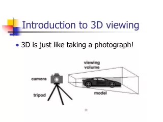
3D Viewing ( From 3D to 2D)
3D Viewing ( From 3D to 2D). Some of the material in these slides have been adapted from the lecture notes of Graphics Lab @ Korea University. Outline. 3D Rendering Pipeline Viewing Transformation Camera Model Parallel Projection Perspective projection Clipping Projecting to viewport.

3D Viewing ( From 3D to 2D)
E N D
Presentation Transcript
3D Viewing(From 3D to 2D) Some of the material in these slides have been adapted from the lecture notes of Graphics Lab @ Korea University
Outline • 3D Rendering Pipeline • Viewing Transformation • Camera Model • Parallel Projection • Perspective projection • Clipping • Projecting to viewport
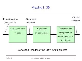
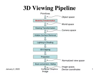
3d Rendering Pipeline 3D Primitives Model Transformation Lighting Viewing Transformation This is a pipelined sequence of operations to draw a 3D primitive into a 2D image for direct illumination Projection Transformation Clipping Viewport Transformation Scan Conversion Image
In Pipeline 3D Primitives Transform into3d world coordinate system Model Transformation Lighting Viewing Transformation Projection Transformation Clipping Viewport Transformation Scan Conversion Image
In Pipeline 3D Primitives Transform into3d world coordinate system Model Transformation Illustrate according to lighting and reflectance Lighting Viewing Transformation Projection Transformation Clipping Viewport Transformation Scan Conversion Image
In Pipeline 3D Primitives Transform into3d world coordinate system Model Transformation Illustrate according to lighting and reflectance Lighting Transform into 3D viewing coordinate system Viewing Transformation Projection Transformation Clipping Viewport Transformation Scan Conversion Image
In Pipeline 3D Primitives Transform into3d world coordinate system Model Transformation Illustrate according to lighting and reflectance Lighting Transform into 3D viewing coordinate system Viewing Transformation Transform into 2D viewing coordinate system Projection Transformation Clipping Viewport Transformation Scan Conversion Image
In Pipeline 3D Primitives Transform into3d world coordinate system Model Transformation Illustrate according to lighting and reflectance Lighting Transform into 3D viewing coordinate system Viewing Transformation Transform into 2D viewing coordinate system Projection Transformation Clip primitives outside window’s view Clipping Viewport Transformation Scan Conversion Image
In Pipeline 3D Primitives Transform into3d world coordinate system Model Transformation Illustrate according to lighting and reflectance Lighting Transform into 3D viewing coordinate system Viewing Transformation Transform into 2D viewing coordinate system Projection Transformation Clip primitives outside window’s view Clipping Transform into viewport Viewport Transformation Scan Conversion Image
In Pipeline 3D Primitives Transform into3d world coordinate system Model Transformation Illustrate according to lighting and reflectance Lighting Transform into 3D viewing coordinate system Viewing Transformation Transform into 2D viewing coordinate system Projection Transformation Clip primitives outside window’s view Clipping Transform into viewport Viewport Transformation Draw pixels(includes texturing, hidden surface etc.) Scan Conversion Image
Transformation 3D Primitives Transform into3d world coordinate system Model Transformation Illustrate according to lighting and reflectance Lighting Transform into 3D viewing coordinate system Viewing Transformation Transform into 2D viewing coordinate system Projection Transformation Clip primitives outside window’s view Clipping Transform into viewport Viewport Transformation Draw pixels(includes texturing, hidden surface etc.) Scan Conversion Image
Transformation P(x, y, z) 3D Object Coordinate 3D Viewing Coordinate Model Transformation 3D World Coordinate Viewing Transformation 3D Viewing Coordinate Projection Transformation 3D Object Coordinate 2D Projection Coordinate ViewportTransformation 3D World Coordinate 2D Device Coordinate p(x’, y’)
Viewing Transformation P(x, y, z) 3D Object Coordinate Model Transformation 3D World Coordinate Viewing Transformation Viewing Transformation 3D Viewing Coordinate Projection Transformation 2D Projection Coordinate Viewport Transformation 2D Device Coordinate p(x’, y’)
Viewing Transformation • Mapping from world to Viewing coordinates • Origin moves to eye position • Up vector maps to Y axis • Right vector maps to X axis Y Camera X Z
Transformation from WC to VC • Transformation sequences 1. Translate the view reference point to the origin of the WC system 2. Apply rotations to align the xv, yv, and zv axes with the world axes General sequence of translate-rotate transformation
Transformation from WC to VC (cont’) • Translation • view reference point(x0, y0, z0) • Rotation • rotate around the world xw axis to bring zv into the xwzw plane • rotate around the world yw axis to align the zw and zv axis • final rotation is about the zw axis to align the yw and yv axis
Transformation from WC to VC (cont’) • Rotation by uvn system • Calculate unit uvn vectors • N : view-plane back normal vector • V : view-up vector • U : perpendicular to both N and V • Form the composite rotation matrix
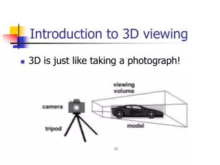
Camera Models • The most common model is pinhole camera • All captured light rays arrive along paths toward focal point without lens distortion (everything is in focus) • Sensor response proportional to radiance • Other models consider… • Depth of field • Motion blur • Lens distortion
Viewing Parameters (Virtual Camera) • Position • Eye position(px, py, pz) • Orientation • View direction(dx, dy, dz) • Up direction(ux, uy, uz) • Aperture (viewing angles) • Field of view(xfov, yfov) • Width, height angles • Film plane • “look at” point • View plane normal
Viewing Angles • Describes the field of view • Like choosing a specific type of lens, e.g., a wide-angle lens or telephoto lens • Width and height angles
Viewing Angle (cont.) • Determines amount of perspective distortion • Small angles result in near-parallel projectors, hence little distortion. Example: telephoto lens • Large angles result in widely varying projectors with large distortion. Example: wide-angle lens
Viewing Angle (cont.) • Aspect Ratio • Ratio of width over height of the screen • 1:1 (square) • 4:3 (NTSC) • 16:9 (HDTV) • 2.35:1 (Widescreen Films) • Represent viewing angles as aspect ratio and height angle • Compute width angle:
Clipping Planes • Restricts visible volume between near and far clipping planes • Objects outside the frustum are not drawn • Objects intersecting the frustum are clipped • Defined as distances dn , df from camera along look vector
Clipping Planes (cont.) • Why do we need near plane • Avoid drawing things too close to camera • They will appear with large distortion, and may block view • Avoid drawing things behind the camera • They will appear upside-down and inside-out • Why do we need far plane • Avoid drawing things too far away • They will complicate the scene • They appear small on the screen anyway • Saving rendering time
Perspective Camera Model • View frustum: a truncated pyramid region that the camera can “see” • 2D view of 3D frustum can be created by projecting onto a film plane
Orthographic Camera Model • Width and height replaces viewing angles • Both width angle and height angle are effectively zero
Viewing Coordinate • Canonical coordinate system • Convention is right-handed (looking down – z axis) • Convention for projection, clipping, etc. Viewing up vector maps to Y axis Y Viewing back vector maps to Z axis (pointing out of page) Viewing right vector maps to X axis X
Viewing Transformation • Transformation matrix maps camera basis vectors to canonical vectors in viewing coordinate system (0, 1, 0) Back Up Matrix (1, 0, 0) Eye Right (0, 0, 1)
Viewing Transformation P(x, y, z) 3D Object Coordinate Model Transformation 3D World Coordinate Viewing Transformation 3D Viewing Coordinate Projection Transformation Projection Transformation 2D Projection Coordinate Viewport Transformation 2D Device Coordinate p(x’, y’)
Projection • General definition • Transform points in n-space to m-space(m<n) • In computer graphics • Map viewing coordinates to 2D screen coordinates
Planar geometric projection Parallel Perspective Orthographic Oblique One-point Three-point Two-point Top Axonometric Cabinet Other Front Cavalier Side Taxonomy of Projections
Parallel & Perspective Projections Perspective Parallel A A A A Centre of Projection. B B B Centre of Projection at infinity B
Planar geometric projection Parallel Perspective Orthographic Oblique One-point Three-point Two-point Top Axonometric Cabinet Other Front Cavalier Side Taxonomy of Projections
Parallel Projection • Center of projection is at infinity • Direction of projection (DOP) same for all points DOP View Plane
Orthographic & Oblique • Orthographic parallel projection • the projection is perpendicular to the view plane
Orthographic Projections • DOP perpendicular to view plane
Orthographic Projections • DOP perpendicular to view plane Front Side Top
Planar geometric projection Parallel Perspective Orthographic Oblique One-point Three-point Two-point Top Axonometric Cabinet Other Front Cavalier Side Taxonomy of Projections
Perspective Projection • Map points onto “view plane” along “projectors” emanating from “center of projection”(cop) Projectors Center of Projection View Plane
Perspective Projection • How many vanishing point?
Perspective Projection • How many vanishing point? Three-point perspective
Perspective Projection • How many vanishing point? Three-point perspective Two-point perspective
Perspective Projection • How many vanishing point? Three-point perspective Two-point perspective One-point perspective
Perspective Projection • Compute 2D coordinates from 3D coordinates with similar triangles dn
Perspective Projection • Compute 2D coordinates from 3D coordinates with similar triangles dn (xdn/z, ydn/z) dn/z=xp/x, dn/z=yp/y