Download
1 / 53
550 likes | 1.19k Vues
Learn the pipeline process, projections, and transformations for viewing 3D objects on a 2D image. Explore perspective and parallel projections for realistic visualization. Understand classical viewing techniques and the importance of perspective foreshortening and vanishing points in creating depth cues.

E N D
Unit 43D Viewing PipelinePart - 2 Projections
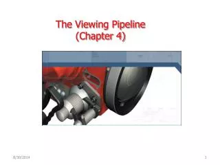
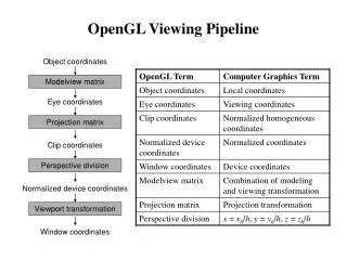
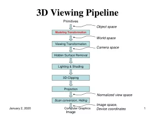
3D Viewing Pipeline Primitives Object space Modeling Transformation World space Viewing Transformation Camera space Hidden Surface Removal Lighting & Shading 3D-Clipping Projection Normalized view space Scan conversion, Hiding Image space, Device coordinates Balwinder Kaur, Assistant Professor, LPU. Image
Contents Introduction Perspective Projections Parallel Projections
Viewing and Projection • Camera Analogy: 1. Set up your tripod and point the camera at the scene (viewing transformation). 2. Arrange the scene to be photographed into the desired composition (modeling transformation). 3. Choose a camera lens or adjust the zoom (projection transformation). 4. Determine how large you want the final photograph to be - for example, you might want it enlarged (viewport transformation). Balwinder Kaur, Assistant Professor, LPU.
Picture Plane Objects in World Space Projections • Our 3-D scenes are all specified in 3-D world coordinates • To display these we need to generate a 2-D image - project objects onto a picture plane • So how do we figure out these projections? Balwinder Kaur, Assistant Professor, LPU.
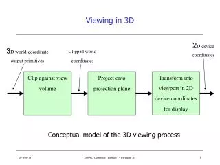
Projections • Projection is just one part of the process of converting from 3-D world coordinates to a 2-D image 3-D world coordinate output primitives Clip against view volume Project onto projection plane Transform to 2-D device coordinates 2-D device coordinates Balwinder Kaur, Assistant Professor, LPU.
Projection Transformation Balwinder Kaur, Assistant Professor, LPU.
Projections • There are two broad classes of projection: • Parallel: Typically used for architectural and engineering drawings • Perspective: Realistic looking and used in computer graphics Perspective Projection Parallel Projection Balwinder Kaur, Assistant Professor, LPU.
Classical viewing Viewing requires three basic elements • One or more objects • A viewer with a projection surface • Projectors that go from the object(s) to the projection surface Classical views are based on the relationship among these elements • The viewer picks up the object and orients it how she would like to see it Each object is assumed to constructed from flat principal faces • Buildings, polyhedra, manufactured objects Balwinder Kaur, Assistant Professor, LPU.
Classical Projections Balwinder Kaur, Assistant Professor, LPU.
Projections Balwinder Kaur, Assistant Professor, LPU.
Contents Introduction Perspective Projections Parallel Projections
Perspective Projections • Perspective projections are much more realistic than parallel projections and are used by artists. Balwinder Kaur, Assistant Professor, LPU.
Y-axis Object point Projected point Projector View Plane COP Z-axis Perspective Projections • Perspective projections are described by • Centre of projection: Eye of artists or lens of camera • View Plane: Plane containing canvas or film strip or frame buffer • A ray called projector is drawn from COP to object point, its intersection with view plane determines the projected image point on view plane. X-axis Balwinder Kaur, Assistant Professor, LPU.
Perspective Projection Balwinder Kaur, Assistant Professor, LPU.
Parallel Projections Balwinder Kaur, Assistant Professor, LPU.
Perspective Projections • There are a number of different kinds of perspective views • The most common are one-point and two point perspectives Balwinder Kaur, Assistant Professor, LPU.
Perspective Projections • Perspective drawings are characterised by • Perspective foreshortening • Vanishing points • View Confusion • Topological Distortion • These are also known as Perspective Anomalies. • These anomalies enhance realism in terms of depth cues, but distorts the actual size, shape and relationship between parts of object. Balwinder Kaur, Assistant Professor, LPU.
Perspective Projections 1. Perspective foreshortening: an illusion that objects and lengths appear smaller as their distance form COP increases. • We can see three balls have different dimensions, since they placed at different distances they are projected to same length Y-axis Z-axis COP(0,0,-d) Balwinder Kaur, Assistant Professor, LPU.
Perspective Projections • Increasing the field of view angle increases the height of the view plane and so increases foreshortening Balwinder Kaur, Assistant Professor, LPU.
Perspective Projections • The amount of foreshortening that is present can greatly affect the appearance of our scenes Balwinder Kaur, Assistant Professor, LPU.
Y-axis COP (0,0,-d) L1 L2 L’1 L’2 X-axis O Z-axis Perspective Projections 2. Vanishing points: An illusion that certain sets of parallel lines appear to meet at a point (called vanishing point). • These are those lines that are not parallel to view plane i.e. lines that are not to view plane normal. • Principal vanishing points are formed by apparent intersection of lines parallel to one of the three principal axes. • The number of principal vanishing points is determined by the number of principal axis intersected by the view plane. Balwinder Kaur, Assistant Professor, LPU.
Perspective Projections (from Donald Hearn and Pauline Baker) Balwinder Kaur, Assistant Professor, LPU.
Classes of Perspective Projection • One-Point Perspective • Two-Point Perspective • Three-Point Perspective Balwinder Kaur, Assistant Professor, LPU.
One-Point Perspective Balwinder Kaur, Assistant Professor, LPU.
Two-point perspective projection: • This is often used in architectural, engineering and industrial design drawings. Balwinder Kaur, Assistant Professor, LPU.
Three-point perspective projection • Three-point perspective projection is used less frequently as it adds little extra realism to that offered by two-point perspective projection Balwinder Kaur, Assistant Professor, LPU.
L2 Y-axis L1 COP(0,0,-d) L’1 L’2 X-axis O Z-axis Perspective Projections 3. View Confusion: An object behind the COP is projected upside down and backward onto the view plane. Balwinder Kaur, Assistant Professor, LPU.
P1 Y-axis P3 COP(0,0,-d) P2 ∞ ∞ P’1 P’2 X-axis O Z-axis Perspective Projections 4. Topological Distortion: All points lying on the plane parallel to view plane and passing through the COP are projected to ∞ by the perspective transformation. • This may make a finite line segment to appear as two infinite rays. Balwinder Kaur, Assistant Professor, LPU.
Perspective Projections Balwinder Kaur, Assistant Professor, LPU.
Perspective Projections • Although a perspective projection is set up by specifying the position and size of the view plane and the position of the projection reference point called COP • However, this can be kind of awkward Balwinder Kaur, Assistant Professor, LPU.
Perspective Projections • The field of view angle can be a more intuitive way to specify perspective projections • This is analogous to choosing a lense for a camera Balwinder Kaur, Assistant Professor, LPU. Field of view
Perspective Projections • We need one more thing to specify a perspective projections using the filed of view angle • The aspect ratio gives the ratio between the width sand height of the view plane Balwinder Kaur, Assistant Professor, LPU.
Contents Introduction Perspective Projections Parallel Projections
Parallel Projections • Parallel projections are used by drafter and engineers to create working drawings of an object as they preserve scale and shape • These are described by • Viewing Direction: which describe the direction of projection • View Plane: Plane containing canvas or film strip or frame buffer • A ray called projector is drawn || to Viewing direction and passing through object point, its intersection with view plane determines the projected image point on view plane. Y-axis Object Viewing Direction Object’ View Plane X-axis Balwinder Kaur, Assistant Professor, LPU. Z-axis
Parallel Projection • Center of projection is at infinity • Direction of projection (DOP) same for all points View Plane DOP Balwinder Kaur, Assistant Professor, LPU.
Parallel Projections Balwinder Kaur, Assistant Professor, LPU.
Orthographic Projections • DOP perpendicular to view plane Front Top Side Balwinder Kaur, Assistant Professor, LPU.
Oblique Projections • DOP not perpendicular to view plane Cavalier (DOP = 45o) Cabinet (DOP = 63.4o) Balwinder Kaur, Assistant Professor, LPU.
Cavalier Projection- It is obtained when the angle between the oblique projectors and the plane of projection is 45 degree and the foreshortening factors for all three principal directions are equal. • In Cavalier projection , the resulting figure is too thick. Balwinder Kaur, Assistant Professor, LPU.
Cabinet Projection- It is used to correct the deficiency that is produced by Cavalier projection. • An oblique projection for which the foreshortening factor for the edge perpendicular to the plane of projection is one-half is called Cabinet projection. • For a cabinet projection, the angle between the projectors and the plane of projection is 63.43. Balwinder Kaur, Assistant Professor, LPU.
Parallel Projections Oblique Projection • Identify type parallel projections Orthographic Projection Balwinder Kaur, Assistant Professor, LPU. Isometric Projection
Parallel Projections • Isometric projections have been used in computer games from the very early days of the industry up to today Q*Bert Sim City Virtual Magic Kingdom BalwinderKaur, Assistant Professor, LPU.
Auxiliary View An auxiliary view is an orthographic view taken in such a manner that the lines of sight are not parallel to the principal projection planes (frontal, horizontal, or profile). There are an infinite number of possible auxiliary views of any given object. Principal faces of the object are not parallel to PP planes. Balwinder Kaur, Assistant Professor, LPU.
Why Auxiliary View? Balwinder Kaur, Assistant Professor, LPU.
Why Auxiliary View? Balwinder Kaur, Assistant Professor, LPU.
Why Auxiliary View? Inclined planes and oblique lines do not appear true length or true size in any of the principle planes of projection To determine the true length of an oblique line or the true size of an inclined plane, an auxiliary view must be created. The auxiliary view shows the true shape and size of circular shapes. Balwinder Kaur, Assistant Professor, LPU.
Orthogonal: • glMatrixMode(GL_PROJECTION); • glLoadIdentity(); • Orthogonal: 1. glOrtho(left, right, bottom, top, near, far); 2. gluOrtho2D(left, right, bottom, top); Balwinder Kaur, Assistant Professor, LPU.