Download
1 / 30
320 likes | 614 Vues
The Viewing Pipeline ( Chapter 4). Overview. OpenGL viewing pipeline : Modelview matrix Projection matrix Parallel and perspective projections Viewport matrix. OpenGL Window-to-Viewport Transformation. OpenGL will clip all primitives that lie outside the world window

E N D
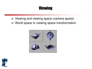
Overview • OpenGLviewing pipeline: • Modelviewmatrix • Projectionmatrix • Parallel and perspective projections • Viewportmatrix
OpenGL Window-to-Viewport Transformation • OpenGLwill clipall primitives that lie outside theworldwindow • Primitives are displayed in aviewportof thescreen window • The window-to-viewporttransformation transformsprimitives fromworld coordinatesto viewport coordinates
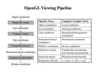
OpenGL Viewing Pipeline • Thewindow-to-viewporttransformation consists of a number of parts: theviewingpipeline: glTranslate*/glRotate*/glScale*glLoadMatrix*/glMultMatrix*gluLookAt gluOrtho2DglOrthogluPerspectiveglFrustum glViewport
The Modelview Matrix • A 3-D to 3-D transformation • Combines effect ofmodellingtransformations andviewpoint • Modelling transformations: • What transformations are applied to each primitive to construct the scene? • Viewing Trasformations: • Where are we viewing the scene from?
The Modelview Matrix • First we need to tellOpenGLthat we want tospecify themodelview matrix: • glMatrixMode(GL_MODELVIEW) • Then we can manipulate the currentmodelviewmatrixusing: • glTranslate* • glRotate* • glScale* • glLoadMatrix* • glMultMatrix* • gluLookAt
The Modelview Matrix • gluLookAt(x0, y0, z0, xref, yref, zref, Vx, Vy, Vz) • Specifies the position/direction/orientation of the ‘camera’ • Position of camera is(x0, y0, z0)in world coordinates • Camera points towards(xref, yref, zref)in worldcoordinates • The vector(Vx, Vy, Vz)specfies the ‘up’ direction forthe camera
The Modelview Matrix - Example glMatrixMode(GL_MODELVIEW); glLoadIdentity(); gluLookAt(8,8,8,0,0,0,0,0,1); glutSolidTorus(1, 2.0, 10, 20);
The Modelview Matrix - Example glMatrixMode(GL_MODELVIEW); glLoadIdentity(); glTranslated(300.0, 200.0, 0.0); // translate all primitives to this point glRecti(-30,-30,30,30); // 60 by 60 square at origin glTranslatef(100,0,0); // this square will be translated glRotatef(45,0,0,1); // and rotated glRecti(-30,-30,30,30); // 60 by 60 square at origin glFlush(); // send all output to display
The Modelview Matrix Stack - Example glMatrixMode(GL_MODELVIEW); glLoadIdentity(); glTranslatef(200,200,0); // translate all rectangles … glPushMatrix(); // save rotation glRotatef(45,0,0,1); //rotate this one glRecti(0,0,50,50); // draw rectangle glPopMatrix(); // restore rotation glPushMatrix(); // save rotation glTranslatef(100,0,0); // translate this one glRotatef(70,0,0,1); // and also rotate it glRecti(0,0,50,50); // draw rectangle glPopMatrix(); // restore rotation glFlush(); // send all output to display
The OpenGL Matrix Stacks • For each matrix in theviewing pipeline,OpenGLmaintains amatrix stack • Thecurrent matrixis the one on top of the stack • Manipulating the matrix stack: • glPushMatrix() • Current matrix copied to second position on stack • All other matrices on stack move down one place • glPopMatrix() • Current matrix is destroyed • All other matrices move up one position on stack
Image plane Image plane Projection Matrices • Projection matricestransform3-Dcoordinatesonto a2-D image plane • 2 basic types of projection: Perspective projection Parallel projection Projection lines are parallel Projection lines converge to a point
Orthographic (or orthogonal) projection Oblique projection Image plane Image plane Projection lines are parallel and perpendicular to image plane Projection lines parallel but not perpendicular Parallel Projections • Objects further from viewer do not appear smaller • Common in CAD applications • Parallel projectionscan be either:
Centre of projection Image plane Perspective Projections • Projection linesconverge at thecentre of projection • Objects that are further away appear smaller • Perspective projectionscan be specified by: • Centre of projection • Camera direction(look vector) • Camera orientation(‘up’ vector) • Height/width of image plane(viewing angles)
Perspective Projections • View angledetermines thedegree of zoom • Like a cameraman changing the camera lens • Narrow angle: high zoom,little depth effect • Wide angle: low zoom,perspective distortion • For a perspective projection we typically have twoviewangles: • Width angle • Height angle
Up vector Look vector Position Perspective Projections • Look vectordetermines the direction thecamera is pointing • Can be any vector in 3-D space • Up vectordetermines the orientation of the camera • E.g. are we holding the camera horizontally/vertically/in between? • Position specified in aright-handedcoordinate system, e.g.
Projections - Clipping Planes • Most graphics packages will define near and farclippingplanes • Volume of space between near and farclipping planesdefines what the camera can ‘see’ • Objects outside of clipping planes will not get drawn • Intersecting objectswill beclipped
Projections – View Volumes • Theview volumeof a camera is a specification of a bounded space that the camera can ‘see’ • View volumecan be specified by: • Camera position, look vector, up vector, image plane aspect ratio, height angle, clipping planes (near/far)
Projections – Perspective Projection View Volume • Perspective projection view volume forms afrustum
Projections – Orthogonal Projection View Volume • Orthographic projection view volume forms acuboid
The Projection Matrix • A 3-D to 2-D transformation: • Orthographicprojection • Perspectiveprojection • InOpenGL: • Thecentre of projectionis theoriginof theviewingcoordinate system(i.e. after themodelviewmatrix) • The view direction (look vector) is the negative z-axis • The ‘up’(‘up’ vector) is the positive y-axis • Specifying theprojection matrix: • gluOrtho2D • glOrtho • gluPerspective • glFrustum
The Projection Matrix • gluOrtho2D (xwmin, xwmax, ywmin, ywmax) • Orthographic projection • Intended for use with 2-D graphics • Defines aworld windowfor clippingthat will be mapped to the specifiedviewport • No nearandfar clipping planes
The Projection Matrix • glOrtho (xwmin, xwmax, ywmin, ywmax, dnear, dfar) • Orthographic projection • Intended for use with 3-D graphics • Defines aworld windowfor clippingthat will be mapped to the specifiedviewport • Can also specifynear andfar clipping planes: • dnearanddfarare the distances of the clipping planes fromthe viewing coordinate origin along the z-axis • Near clipping planeis theimage plane
theta = height angle The Projection Matrix • gluPerspective (theta, aspect, dnear, dfar) • Perspective projection • thetais theheight anglein degrees • aspect is the ratio of the width to the height of theimage plane (theaspect ratio) • Centre of projectionis the origin of the viewingcoordinate system • dnear, dfarare distances of clipping planes from centre of projection along z-axis • Image planeis the near clipping plane
Height angle The Projection Matrix • glFrustum (xwmin, xwmax, ywmin, ywmax, dnear, dfar) • Perspective projection • Corners ofnear clipping planehave the followingcoordinates in theviewing coordinate system: • (xwmin, ywmin, -dnear) • (xwmin, ywmax, -dnear) • (xwmax, ywmin, -dnear) • (xwmax, ywmax, -dnear) • Centre of projectionis theorigin of the viewing coordinate system • Image planeis the nearclipping plane
The Projection Matrix - Examples • gluOrtho2Dexample: • All primitives with(x,y)coordinates between(0,0)and(640,480)will be displayed • glOrthoexample: • Defines a24x24x30view volumewith theimageplaneat the origin: glMatrixMode(GL_PROJECTION); glLoadIdentity(); gluOrtho2D(0.0, 640.0, 0.0, 480.0); glMatrixMode(GL_PROJECTION); glLoadIdentity(); glOrtho(-12, 12, -12, 12, 0, 30); // left, right, bottom, top, near, far
The Viewport Matrix • Determines theregionof thescreenwindowto be used for drawing • Specifying theviewport matrix: • glViewport(xPos, yPos, xSize, ySize) • Viewport has bottom-left corner at(xPos,yPos),and has a size in pixels of(xSize,ySize)
The Viewport Matrix - Example void drawObjects() { glMatrixMode(GL_MODELVIEW); glLoadIdentity(); glutWireTorus(1, 2.0, 10, 20); glTranslated(7.0,0.0,0.0); glutWireTeapot(3); } /* GLUT callback Handlers */ void display() { glClear(GL_COLOR_BUFFER_BIT); glViewport(0, 0, 320, 240); drawObjects(); glViewport(320, 0, 320, 240); drawObjects(); glViewport(0, 240, 320, 240); drawObjects(); glViewport(320, 240, 320, 240); drawObjects(); glFlush(); // send all output to the display }
Specifying the Screen Window • Thescreen windowis the window onyour monitor thatOpenGLuses todraw primitives • Sizeandpositionofscreen windowspecified by: • glutInitWindowSize(width,height) • Width and height of window in pixels • glutInitWindowPosition(x,y) • Position (x,y) in pixels from the top-left of the screen
Summary • TheOpenGL viewing pipeline: • A series of matrix transformations that all primitivesundergo • Modelview matrix: combines modelling and viewingtransforms • Projection matrix: projects 3-D viewing coordinatesonto image plane • Viewport matrix: selects the part of the display window to use for drawing