Sublevel Caving Blast Dynamics
Sublevel Caving Blast Dynamics. Research Objectives and Outcomes. Objectives. Tools. Outcomes. Improved understanding of SLC blast dynamics. Improved understanding SLC blast dynamics, disturbed flow behaviour, and blast-flow interaction. Hybrid Stress Blast Model (HSBM).
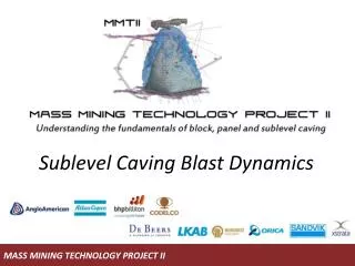

Sublevel Caving Blast Dynamics
E N D
Presentation Transcript
Research Objectives and Outcomes Objectives Tools Outcomes Improved understanding of SLC blast dynamics Improved understanding SLC blast dynamics, disturbed flow behaviour, and blast-flow interaction Hybrid Stress Blast Model (HSBM) Improved operational ring recovery through modified blast design (guidelines) Improved understanding of the impact of SLC blastdynamics on flow behaviour 3D Discrete Element Code (3DEC) Improved mine scale modelling of SLC flow behaviour Improved model predictive capability for LOM flow simulation REBOP SLC
Outline • Hybrid Stress Blast Model (HSBM) code history. • HSBM model validation • HSBM SLC ring results (Ridgeway and Kiruna). • SLC ring blast conceptual model. • SLC ring blast design guidelines. • Potential SLC ring blast design modification. • Strengths and limitations.
HSBM Code History March 2010 September 2010 September 2011 March 2011 V 2.5 V 2.5.1 V 2.5.12 V 2.5.7 SLC Geometry Flexible Boundary Logic CAD Import Improved Flexible Boundary Logic Improved Parallel Processing Improved Flex Boundary Logic Improved Parallel Processing Ridgeway SLC Model (Comparison of 7 and 8 Hole Patterns) Improved Gas Flow Logic Improved Quite Boundary Logic Small Scale Cube Models Kiruna Large Scale Experiments Ridgeway SLC models Kiruna SLC model Ridgeway SLC Model (7 Hole Pattern) Ridgeway SLC Model (Comparison of 7 and 8 Hole Patterns with Backbreak) LKAB SLC Model
HSBM Model Validation • Model validation process ongoing during research period. Validation related to code logic, large scale experimental data, and full scale ring data, and included: • Assessment of model output against ‘expected’ results (early code assessment). • Validation of model output against large scale experimental data at Kiruna (burden movement, void formation, fragmentation). • Validation against full scale ring data (marker results – backbreak and extraction zone, observed rock mass damage, blast performance, fragmentation).
The experiments consisted of drilling horizontal blast holes in cross cut pillar noses sub-parallel to the crosscuts. The data collected for this experimental program included: Geometric and geotechnical survey of test site. Measurement of borehole deviation. Blast VOD and vibration monitoring. Propagation of fracturing within and behind the burden (fast sampling TDR). Measurement of burden movement (high shock accelerometers, draw wire gauges, magnetostrictive sensors, laser/fibre sensors, spear gauges, and high speed filming). Kiruna Large Scale Experiments
Large Scale Experiment Results Approximate 1 m void Flex Boundary A Value = 5.5
Modelling Methodology 1 Initial model run to generate backbreak damage Backbreak damage exported into model 2 Second model run incorporating backbreak damage Output model results: – rock mass damage – fragmentation – burden displacement 3
Blast Design Criteria • A request was made in the previous MMT2 meeting to develop a practical engineering tools to be used in production ring design, based upon HSBM results. • The tool does not provide insight into SLC blast dynamics - instead it uses the results from the HSBM to provide an estimate of backbreak and zone of well fragmented rock. • Two methodologies considered: • Holmberg-Persson PPV crtieria and • Energy distribution. • These can be contoured in commercially available software JKSimBlast. • The Ridgeway eight hole design used to assess the two tools.
Holmberg-Persson PPV Criteria Persson et al, 1994
Holmberg-Persson PPV Criteria K and a values derived from PPV vector sum data PPVbreakage = 4 x PPVcrit
Blast Design Criteria Horizontal Section 1 (2 m above drive roof) Blast/Cave Interface Horizontal Section 2 (17 m above drive roof) Blast/Cave Interface Horizontal Section 3 (22 m above drive roof) Micro-fractures Blast/Cave Interface PPV > 4800 mm/s
Blast Design Guidelines S D = Hole Diameter (m) B = Burden (m) S = Hole Spacing (m) B/D Ratio (Emulsion) = 25 (Hustrulid, 2000) HSBM results indicate adequate breakage for this burden by a combination of breakage and backbreak damage (Ridgeway B/D = 25.5) (Kiruna B/D = 26.1) S/B Ratio = 1.1 – 1.4 (Marklund, 1976; Bull and Page, 2000; Hustrulid, 2000; Onederra and Power, 2000) HSBM results indicate adequate breakage (Ridgeway 8 Hole S/B = 1.15 to 1.25) (Kiruna S/B = 1.10 to 1.20) S/B Ratio > 1.4 HSBM results indicate poor breakage in apex region (Ridgeway 7 Hole S/B = 1.40 to 1.55) S S S S S S S S
Blast Design Guidelines Ideal blast design – adequate breakage and burden movement in apex and shoulder regions 2 holes in apex region achieves adequate fragmentation and compaction of cave material 1 hole in apex region results in poor fragmentation and minimal burden movement Higher angle shoulder holes results in improved fragmentation and burden movement Over confinement of low angle shoulder holes results in poor fragmentation and minimal burden movement
Potential Design Modifications Firing Direction B Adequate explosive distribution through centre of ring to achieve burden movement Offset hole geometry between the two blast rings – ‘dice 5’ configuration Offset , alternating 7 and 8 hole blast rings. This would result in improved explosive energy distribution through the ring and reduction in drill cost.
Potential Design Modifications Centre 4 holes detonated on fast delays. Potential to reduce the likelihood of hole failure and increase burden movement 0 ms 0 ms 0 ms 0 ms Blast initiation timing 50 ms 50 ms 5 ms 5 ms 100 ms 100 ms 50 ms 50 ms Potential hole dislocation: partial or non-detonation blast holes (Vibration records RW and Kiruna) 150 ms 150 ms 100 ms 100 ms Lower confinement of shoulder holes due to increased burden movement in centre of ring
Research Strengths • Strengths: • HSBM demonstrated to be a useful tool in the modelling of SLC blast rings. Model takes into account a number of complexities associated with blasting in a semi-confined environment including: • Explosive-rock mass interaction (dilation and extension of existing discontinuities and blast induced intact rock breakage). • Burden movement and associated cave material compaction. • Potential void formation and creation of a higher blasted material porosity region in the centre of the ring. • Impact of poor blast performance on rock fragmentation and porosity. • Blast design methodology related to PPV criteria appears promising in the modelling of ring explosive distribution. • Recommendations with respect to ring design changes to improve blast performance, fragmentation, and porosity.
Research Limitations • Limitations: • HSBM modelling limited to three blast design: • Ridgeway seven hole pattern. • Ridgeway eight hole pattern. • Kiruna eight hole pattern. • HSBM modelling limited to two rock masses: • Ridgeway Volcanics (UCS = 120 MPa, FF/m = 3.5). • Kiruna Magnetite (UCS = 133 MPa, FF/m = 0.5). • Additional blast designs and rock types need to be considered in the modelling and blast design process.
Conclusions • HSBM code applied to SLC blast ring design to model explosive-rock interaction under semi-confined conditions. • HSBM models validated/calibrated against large scale experimental and full scale ring data. • A conceptual model of SLC blast dynamics related to burden movement, fragmentation, porosity, and blast performance is proposed. • Blast design criteria reviewed. • Blast design guidelines reviewed in the literature and compared to HSBM results. • A number of SLC ring blast design changes proposed to improve blast performance.