BEEKeeper Remote Management and Debugging of Large FPGA Clusters
160 likes | 294 Vues
This paper details the BEEKeeper system, an innovative solution for remote management and debugging of large FPGA clusters, particularly in the context of the RAMP project and CASPER initiatives. By leveraging multiple BEE2 modules equipped with Xilinx FPGAs, BEEKeeper improves access and control over remote instruments deployed in radio astronomy. The system features a Mini-module with Ethernet connectivity, allowing for TCP/IP communication, thus facilitating access to individual FPGAs for debugging. This approach mitigates the limitations of traditional JTAG and enhances scalability, providing an efficient pathway for data aggregation and simultaneous multi-FPGA programming.

BEEKeeper Remote Management and Debugging of Large FPGA Clusters
E N D
Presentation Transcript
BEEKeeperRemote Management and Debugging of Large FPGA Clusters Terry Filiba Navtej Sadhal
Background • RAMP: Research Accelerator for Multiple Processors • Large array of Berkeley Emulation Engine (BEE2) modules • Each BEE2 contains 5 Xilinx Virtex II Pro FPGAs • 1 Master (control) FPGA • 4 Slave FPGAs • 2 JTAG serial chains • Master can program slaves over 1 chain • Or slaves can be individually accessed over the other
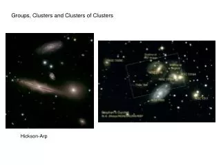
Background • CASPER: Center for Astronomy Signal Processing and Electronics Research • Processing is cheaper than building large antennas • Instruments are remotely deployed at antenna arrays • Using large arrays of BEE2 boards to develop instruments for radio astronomy (currently correlators, beamformers, and spectrometers)
BEE2 Module image from RAMP project: http://ramp.eecs.berkeley.edu/index.php?pictures
RAMP Blue images from RAMP project: http://ramp.eecs.berkeley.edu/index.php?pictures
What is JTAG? image from Wikipedia: http://en.wikipedia.org/wiki/Image:Jtag_chain.svg • Transports data serially throughout multiple chips • TMS : test mode • TCK : clock • TDI : test data in • TDO : test data out
What is JTAG? image from Wikipedia: http://en.wikipedia.org/wiki/Image:Jtag_chain.svg • Not very scalable • Each clock represents 1 bit of data moving through the system • In order to get test data into device 3 it has to go through device 1 and 2 • Only suitable for a few chips daisy-chained together
Background • On-chip debugging with ChipScope • FPGA design can include debugging module • Transmits debugging signal information over JTAG to host computer • Host computer running ChipScope software receives data over parallel or USB cable
Problem • We need to talk to individual FPGAs or boards to use ChipScope • Normal parallel or USB approach is limited • Does not scale • Requires physical access to board
Proposed Solution • Client driver • Intercepts ChipScope software communications and transmits it over TCP/IP • BEEKeeper • Mini-module with Xilinx Spartan 3 FPGA and Ethernet port • MicroBlaze soft core runs C programs • Receives data from host over TCP/IP and passes it on to BEE2 over JTAG
BEEKeeper Module image from Avnet: http://www.em.avnet.com/img_shared/evk/df2df2usa/spartan3miniphoto.jpg
Proposed Solution • User can change which BEE2 is being accessed by a local software switch • Software can multiplex across many BEE2s to aggregate data • User can remotely access BEE2s from anywhere with an Internet connection • Ideal for CASPER project
Future Work • Extend the client software to connect to multiple boards simultaneously • Program multiple FPGAs at once • Debug multiple FPGAs at once • Need a way to aggregate the data received from the servers • Integrate BEEKeeper hardware onto board to be debugged (BEE)