10.3 Images in Concave Mirrors
250 likes | 846 Vues
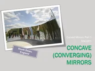
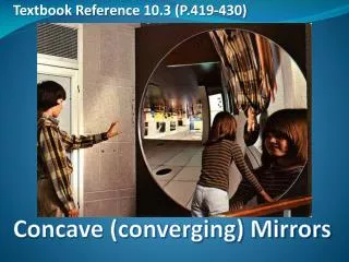
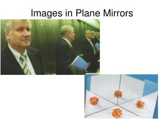
10.3 Images in Concave Mirrors. Concave Mirror. Unlike a plane mirror, a curved mirror produces an image that is a different size, shape, and/or orientation. Imagine remove a square out of a basketball and covering this region with a mirror The inner region produces a concave mirror.

10.3 Images in Concave Mirrors
E N D
Presentation Transcript
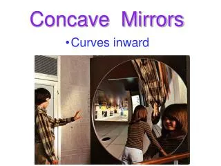
Concave Mirror • Unlike a plane mirror, a curved mirror produces an image that is a different size, shape, and/or orientation. • Imagine remove a square out of a basketball and covering this region with a mirror • The inner region produces a concave mirror
Images in a Concave Mirror • In a concave mirror, the images towards the edges of the mirror produce increasingly more distorted images
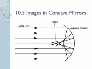
Drawing Ray Diagrams for Concave Mirrors • When dealing with a curved mirror, you should treat each curved surface as many small, flat mirrors (Figure 10.20A). • Each of the normal’s (in blue) intersect at a point called the centre of curvature (c)
Draw Ray Diagrams for Concave Mirrors • The thick horizontal normal that touches the centre of the mirror is called the principal axis. • The point at which the principal axis cuts the centre of the mirror is called the vertex (V). principal axis. V
Draw Ray Diagrams for Concave Mirrors • If an incident ray passes through the centre of curvature, the ray will reflect back onto itself. • The angle of incidence is zero, therefore the angle of reflection is zero • This holds true for all rays passing through point “c”. V
Draw Ray Diagrams for Concave Mirrors • An incident ray that is near and parallel to the principal axis will reflect and intersect at the focal point (F). • All incidence rays that are near and parallel to the principal axis will reflect through point “F”. • Any rays that pass through point “F” will reflect and travel parallel to the principal axis. V
Draw Ray Diagrams for Concave Mirrors • The distance between the focal point (f) and the vertex (v) is called the focal length. V
Drawing an object between the focal point and the mirror • When an object is placed between the focal point and the mirror, the image produced is an uprightvirtual image that is enlarged. • Take 8 minutes to follow all the steps on page 422. • You may be asked to come to the board and complete one of these steps
An object between the focal point and the centre of curvature • When an object is between the focal point and the centre of curvature, the image produced is an invertedreal image that is enlarged. • Take 8 minutes to follow all the steps on page 423. • You may be asked to come to the board and complete one of these steps
An object between the focal point and the centre of curvature
An object beyond the centre of curvature • When an object is beyond the centre of curvature, the reflection is smaller and inverted as a real image. • Follow page 424 and draw the reflection for an object that is beyond the centre of curvature.
Mirror and Magnification Equations • The characteristics of an image can also be predicted by using two equations: • Mirror Equation: • Allows us to determine the focal point, distance of the image, or the distance of the object • Must know two of the three variables in order to solve the third • Magnification Equation: • Allows us to determine the height of the object or the height of the image. • This equation is usually used following the mirror equation
Mirror Equation • The mirror equation allows you to calculate the location of an image • The mirror equation is seen below • do represents the distance of the object • direpresents the distance of the image • f represents focal length
Mirror Equation • If the image distance di is negative, then the image is behind the mirror (a virtual image)
Mirror Equation Question • A concave mirror has a focal length of 12 cm. An object with a height of 2.5 cm is placed 40 cm in front of the mirror. • Calculate the image distance. • Is the image in front of the mirror or behind? How do you know this?
Magnification Equation • The magnification (m) tells you the size, or height of the image relative to the object, using object and image distances. • Therefore, in order to use this equation the distance of the object and image must be known.
Magnification Equation • If the image height hi is negative, the image is inverted relative to the object.
Magnification Equation Question • A concave mirror has a focal length of 12 cm. An object with a height of 2.5 cm is placed 40 cm in front of the mirror. The image distance has been calculated to be 17.14 cm. • What is the height of the image? • Is the image inverted? Explain.
Additional Problems • Questions 1-5 on page 427 • Questions 1-8 on page 430