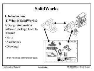
SolidWorks
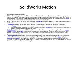
Image courtesy of Innovation Engineering Inc. SolidWorks. September 10, 2008. SolidWorks Everywhere in Consumer Products. CLIPPERS Sweden. STAIRLIFT UK. PERFUME France. FAX & COPIER Korea. SHOWER UK. TELEPHONE Germany. BATHROOM Spain. STAIRS Italy. COMPUTER USA. FURNITURE

SolidWorks
E N D
Presentation Transcript
Image courtesy of Innovation Engineering Inc. SolidWorks September 10, 2008
SolidWorks Everywhere in Consumer Products CLIPPERS Sweden STAIRLIFT UK PERFUME France FAX & COPIER Korea SHOWER UK TELEPHONE Germany BATHROOM Spain STAIRS Italy COMPUTER USA FURNITURE Spain AIR CONDITIONING Japan VACUUM CLEANER Italy TELEPHONE South Korea KITCHEN USA HANDLES USA LOCK USA
Industry Example: Trek Bikes • Company: • Designs, manufactures, and markets bicycles and bike accessories. • Challenge: • Heightened expectation for quality (Lance Armstrong) • Integrate Design and Manufacturing • Increased market demand • SolidWorks Benefits: • Shortened design cycle by 50% • Improved product quality • Doubled throughput of new products (100% increase) By providing integrated design, analysis, manufacturing, and communication tools, SolidWorks software has enabled Trek Bicycles to double its design throughput while improving quality and increasing innovation. "SolidWorks has the most solid business experience in actual production settings. Because we wanted to use 3D data at more points in our development process, we chose the system with the most momentum, knowing that it would produce additional opportunities for integration." Steve Baumann, Industrial Design Manager
Industry Example: Kneissl • Company: • Located in Switzerland, Kneissl manufactures skis and tennis rackets • Challenge: • Replace 2D AutoCad with 3D capabilities • transform an idea from design to production quickly • Affortability • SolidWorks Benefits: • Can quickly conceptualize • Makes production of final product much easier • Low cost "In SolidWorks, we can give free rein to our creativity." Richard Holzner, Director of R&D Ski
Using the Interface • Use windows to view files. • Use the mouse to select buttons, menus, and model elements. • Run programs — like SolidWorks mechanical design software. • Find, open, and work with files. • Create, save, and copy files. The interface is how you interact with the computer in the following ways:
Microsoft® Windows® • SolidWorks runs on the Microsoft Windows graphical user interface. • Windows let you see the work of an application program. • Panels are sub sections of windows. • Illustration shows one window with two panels.
Using the SolidWorks Interface • SolidWorks windows display graphic and non-graphic model data. • Toolbars display frequently used commands.
Left Side of SolidWorks Window • Property Manager • Configuration Manager • FeatureManager design tree™
Toolbars Buttons for frequently used commands. • You canselect the toolbars to display. • View / Toolbars
Getting Help To view comprehensive online help: • Click . • Select Help, SolidWorks Help Topics. • Help displays in a separate window.
What is SolidWorks? • SolidWorks is design automation software. • In SolidWorks, you sketch ideas and experiment with different designs to create 3D models. • SolidWorks is used by students, designers, engineers, and other professionals to produce simple and complex parts, assemblies, and drawings.
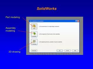
The SolidWorks Model • The SolidWorks model is made up of: • Parts • Assemblies • Drawings
The SolidWorks Model Part Part Drawing Drawing Assembly
Features • Features are the building blocks of the part. • Features are the shapesand operationsthat construct the part.
Examples of Shape Features • Base Feature • First feature in part. • Created from a 2D sketch. • Forms the work piece to which other features are added.
Examples of Shape Features • Boss feature • Adds material to part. • Created from 2D sketch.
Examples of Shape Features • Cut feature • Removes material from part. • Created from 2D sketch.
Examples of Shape Features • Hole feature • Removes material. • Works like more intelligent cut feature. • Corresponds to process such as counter-sink, thread, counter-bore.
Examples of Shape Features • Fillet feature • Used to round off sharp edges. • Can remove or add material. • Outside edge (convex fillet) removes material. • Inside edge (concave fillet) adds material.
Examples of Shape Features • Chamfer feature • Similar to a fillet. • Bevels an edge rather than rounding it. • Can remove or add material.
Sketched Features & Operation Features • Sketched Features • Shape features have sketches. • Sketched features are built from 2D profiles. • Operation Features • Operation features do not have sketches. • Applied directly to the work piece by selecting edges or faces.
Select the sketch plane Sketch the 2D profile Extrude the sketch Resulting base feature To Create an Extruded Base Feature: • Select a sketch plane. • Sketch a 2D profile. • Extrude the sketch perpendicular to sketch plane.
To Create a Revolved Base Feature: • Select a sketch plane. • Sketch a 2D profile. • Sketch a centerline (optional). • Revolve the sketch arounda sketch line or centerline. Centerline (optional)
FeatureManager design tree Graphics Area Terminology: Document Window • Divided into two panels: • Left panel contains the FeatureManager® design tree. • Lists the structure of the part, assembly or drawing. • Right panel contains the Graphics Area. • Location to display, create, and modify a part, assembly or drawing.
Terminology: User Interface MenuBar Toolbar Task pane CommandManager Drawingdocumentwindow Partdocumentwindow Status bar Toolbar
Terminology: PropertyManager Preview Confirmationcorner PropertyManager Handle
Axis Plane Origin Terminology: Basic Geometry • Axis - An implied centerline that runs through every cylindrical feature. • Plane - A flat 2D surface. • Origin - The point where the three default reference planes intersect. The coordinates of the origin are: (x = 0, y = 0, z = 0).
Vertex Edge Edge Faces Terminology: Basic Geometry • Face – The surface or “skin” of a part. Faces can be flat or curved. • Edge – The boundary of a face. Edges can be straight or curved. • Vertex – The corner where edges meet.
Features and Commands Base feature • The Base feature is the first feature that is created. • The Base feature is the foundation of the part. • The Base feature geometry for the box is an extrusion. • The extrusion is named Extrude1.
Features and Commands Features used to build the box are: • Extruded Base feature • Fillet feature • Shell feature • Extruded Cut feature 1.Base Feature 2.Fillet Feature 3.Shell Feature 4.Cut Feature
Features and Commands To create the extruded base feature for the box: • Sketch a rectangular profile on a 2D plane. • Extrude the sketch. • By default extrusions are perpendicular to the sketch plane.
Features and Commands Fillet feature • The fillet feature rounds the edges or faces of a part. • Select the edges to be rounded. Selecting a face rounds all the edges of that face. • Specify the fillet radius. Fillet
Wall Thickness Features and Commands Shell feature • The shell feature removes material from the selected face. • Using the shell feature creates a hollow box froma solid box. • Specify the wall thicknessfor the shell feature.
Features and Commands To create the extruded cut feature for the box: • Sketch the 2D circular profile. • Extrude the 2D Sketch profile perpendicular to the sketch plane. • Enter Through All for the end condition. • The cut penetrates through the entire part.
Dimensions and Geometric Relationships • Specify dimensions and geometric relationships between features and sketches. • Dimensions change the size and shape of the part. • Mathematical relationships between dimensions can be controlled by equations. • Geometric relationships are the rules that control the behavior of sketch geometry. • Geometric relationships help capture design intent.
Dimensions • Dimensions • Base depth = 50 mm • Boss depth = 25 mm • Mathematical relationship • Boss depth = Base depth 2
Document Properties • Accessed through the Tools, Options menu. • Control settings like: • Units: English (inches) or Metric (millimeters) • Grid/Snap Settings • Colors, Material Properties and Image Quality
System Options • Accessed through the Tools, Options menu. • Allow you to customize your work environment. • System options control: • File locations • Performance • Spin box increments
View Control Magnify or reduce the view of a model in the graphics area. • Zoom to Fit – displays the part so that it fills the current window. • Zoom to Area – zooms in on a portion of the view that you select by dragging a bounding box. • Zoom In/Out – drag the pointer upward to zoom in. Drag the pointer downward to zoom out. • Zoom to Selection – the view zooms so that the selected object fills the window.
Display Modes • Illustrate the part in various display modes. Wireframe Hidden lines Visible Hidden Lines Removed Shaded Shaded With Edges
Isometric View Top View Back View Left View Front View Right View Bottom View Standard Views
Front Right Bottom Isometric Top Left Back Normal To (selected plane or planar face) View Orientation Changes the view display to correspond to one of the standard view orientations.
Isometric View • Displays the part with height, width, and depth equally foreshortened. • Pictorial rather than orthographic. • Shows all three dimensions – height, width, and depth. • Easier to visualize than orthographic views.
The Status of a Sketch • Under defined • Additional dimensions or relations are required. • Under defined sketch entities are blue (by default). • Fully defined • No additional dimensions or relationships are required. • Fully defined sketch entities are black (by default). • Over defined • Contains conflicting dimensions or relations, or both. • Over defined sketch entities are red (by default).
Class and Homework • Work through Chapters 4&5 and complete the exercises at the end of each chapter. These are due Tuesday of next week.