Advanced Modeling of Heat Release, Cylinder Volume, and Emissions in Combustion Engines
This document outlines methodologies for modeling key aspects of combustion engine performance. It covers heat release modeling by differentiating the ideal gas law concerning crank angle and deriving instantaneous changes in pressure and temperature, integrated over crank angle for net heat transfer. Further, it discusses cylinder volume calculations using engine geometry, mass fraction burned, heat transfer modeling, and a two-zone model for burned-zone temperature. Additionally, it addresses NO formation and hydrocarbon emissions modeling, including mechanisms of HC formation and the impact of pressure and temperature on emissions.

Advanced Modeling of Heat Release, Cylinder Volume, and Emissions in Combustion Engines
E N D
Presentation Transcript
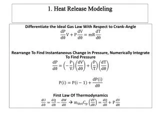
1. Heat Release Modeling Differentiate the Ideal Gas Law With Respect to Crank-Angle Rearrange To Find Instantaneous Change in Pressure, Numerically Integrate To Find Pressure First Law Of Thermodynamics
Rearrange to Find Instantaneous Change In Temperature, Integrate To Find Temperature Change In Net Heat Transfer As A Function Of Crank-Angle
2. Cylinder Volume Modeling • The engine volume (as a function of crank angle) can be calculated using engine geometry =clearance volume =bore =connecting rod length =crank radius (1/2 of stroke) =instantaneous distance between piston pin and crank axis
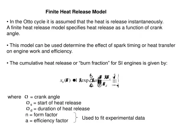
Weibe function is used to predict the combustion burn profile =fraction of fuel mass burned at specific crank angle =Spark advance =Burn duration , = constants fit to a specific engine (approximately 5,2) 3. Mass Fraction Burned Modeling
The equilibrium concentration of is found using the following equilibrium equation: The equilibrium constant can be calculated as a function of the burned zone temperature using the JANAF tables:
Use the following equation to calculate the percentage of dissociation of : Assume that the equilibrium mole fraction of nitrogen is equal to that provided by the atom balance equations. Assume that the composition is frozen at 90% of the peak burned-zone temperature.
This is total crevice emissions index. A further explanation of HC formation mechanisms can be found on the Mindworks website. The peak cylinder pressure and IMEP can be found from the single-zone model. The coolant temperature can be estimated as 350 [K]. The crevice volume can be measured.
8. Hydrocarbon Emissions Model (Oil Layer Absorption and Desorption
The pressure term used in predicting the mass of hydrocarbons can be estimated as an average between the inlet and peak combustion temperatures.