Download
1 / 27
270 likes | 472 Vues
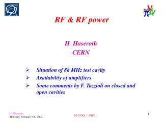
RF & RF power H. Haseroth CERN Situation of 88 MHz test cavity Availability of amplifiers Some comments by F. Tazzioli on closed and open cavities. Situation of 88 MHz test cavity. Power efficiency optimization. using. and. Challenges:. High gradient at low frequency

E N D
RF & RF power H. Haseroth CERN Situation of 88 MHz test cavity Availability of amplifiers Some comments by F. Tazzioli on closed and open cavities MUCOOL / MICE
Situation of 88 MHz test cavity MUCOOL / MICE
Power efficiency optimization using and MUCOOL / MICE
Challenges: • High gradient at low frequency (Kilpatrick: 2.3) sparking: tests • (high) magnetic field lines penetrating the cavities multipactor: computations & tests • large cavity dimensions mechanical stability: computations • field emission induced by lost particles cavity test with beam. MUCOOL / MICE
2. Status of the high gradient test set-up Original system: PS 114 MHz RF cavity for leptons MUCOOL / MICE
88 MHz test cavity MUCOOL / MICE
88 MHz test cavity (made from an 114 MHz structure) Closed gap case E0 = 4 MV/m frep = 1 Hz r/Q = 113 = 180 s tpulse , frep = 1 ms, 1 Hz Ppeak = 1.4 MW Pmean = 1.4 kW Kilp. = 2.3 gap = 280 mm length = 1 m diameter = 1.77 m Open gap case E0 = 4 MV/m frep = 1 Hz r/Q = 107 = 180 s tpulse , frep = 1 ms, 1 Hz Ppeak = 1.5 MW Pmean = 1.5 kW Kilp. = 2.3 gap = 260 mm length = 1 m diameter = 1.77 m MUCOOL / MICE
Asymmetric 88 MHz cavities MUCOOL / MICE
Preliminary parameters of an 88 MHz option for ICE Sketch of a 4 cavities module MUCOOL / MICE
Electrical power and cooling needs for the 88 MHz option in ICE => Advantage of the 10 Hz option Overall needs in infrastructure: H. Ullrich MUCOOL / MICE
An 88 MHz test cavity for high gradient is being prepared (2 MW amplifier driving a modified 114 MHz PS cavity) • High RF gradient without solenoid: end 2001 • RF test with solenoid: mid-2002 Cavity with closed gap: E0 = 4 MV/m frep = 1 Hz r/Q = 113 = 180 s tpulse = 10.5 ms Ppeak = 1.4 MW Pmean = 15 kW Kilp. = 2.3 gap = 280 mm length = 1 m diameter = 1.77 m MUCOOL / MICE
88 MHz test cavity (made from an 114 MHz structure) 88 MHz cavity 2 MW amplifier Nose Cone (closed gap) MUCOOL / MICE
The RF chain up to 20 kW is assembled and will soon be turned-on. Next step will be to set-up the 200 kW driver stage which is already assembled MUCOOL / MICE
The mechanics of the 2 MW final stage is still in preparation. Most pieces are or will soon be available, kapton capacitor, anode resonator, coupling loops, coaxial lines,...] but assembly is still pending. As far as I know, nothing has yet been done to prepare diagnostics (no one available). This work has now a low priority, but we are keen to get results. We estimate that real tests of the full set-up will begin before this summer. (Roland dixit) MUCOOL / MICE
88 MHz test system status and planning SUMMARY First turn-on of the complete amplifier chain: 12/2001 (not yet) Setting-up on dummy load: 03/2002 High gradient in the cavity: 05/2002 Increase of RF power: 10/2002 ? (push or 200k) Test with solenoid: 12/2002 ?? (financing) MUCOOL / MICE
1. Economically relevant parameters • Amplifier cost / unit º Peak & mean RF power • Peak RF power ºGradient & RF frequency • Mean RF power ºPeak RF power & Duty factor • Cavity cost / unit ºGradient & RF frequency • Number of amplifiers & Number of cavities º Gradient in the cavities • Power consumption º Duty factor SUMMARY OF KEY PARAMETERS - Gradient in the cavities (Voltage per cavity) - RF frequency - Duty factor (repetition rate) MUCOOL / MICE
2. Preliminary analysis Effect of the duty factor Case 1: 5 ms useful beam time per second (100 ms bursts at 50 Hz or 500 ms bursts at 10 Hz) Case 2: “refurbished” CERN 200 MHz - 4 MW amplifier (Duty factor = 0.001) MUCOOL / MICE
Effect of the voltage per cavity General considerations Ncav : Number of cavities Vtotal: Total cavities voltage DVcav: RF voltage / cavity Pcav: RF power / cavity Ptotal: Total RF power Case of a limited number of 200 MHz - 4 MW amplifiers MUCOOL / MICE
Economical optimum: number of cavities & number of amplifiers Assumption : Vtotal is imposed Ncav : Number of cavities n: Number of cavities per amplifier Vtotal: Total cavities voltage k: Number of amplifiers DVcav: RF voltage / cavity Ccav: Cavity cost Pcav: RF power / cavity Camp: Amplifier cost Ptotal: Total RF power CRF: Total RF cost Tentative application: get 28 MV with 4 MW amplifiers Camp =Ccavkoptimum ~4, corresponding to 1 cavity per amplifier Camp =2 Ccavkoptimum ~3, corresponding to 1 cavity per amplifier Camp =4 Ccavkoptimum ~2, corresponding to 4 cavities per amplifier MUCOOL / MICE
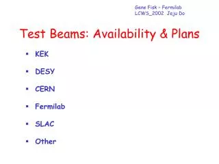
RF–Power Amplifiers available at CERN 200 MHz: 1 amplifier (spare for Linac2) 2 MW, (could be upgraded to 4 MW) 1 amplifier (from Linac1, needs refurbishing for 200 kCHF) 4 MW (FTH triode tube, ex-TH 516, water-cooled version) The first one should be used as driver for the second one Total available power now 4 MW This could go up to a total of 8 MW, provided we find another driver amplifier of several hundred kW MUCOOL / MICE
RF–Power Amplifiers available at CERN 88 MHz: 1 amplifier available 2 MW (FTH triode tube) driver (LHC type, modified) available If amplifier is modified 4 MW achievable, but driver must be pushed 1 amplifier (from Linac1, needs refurbishing for 200 kCHF) 4 MW (pushed) driver needs to be found or the amplifier above must be used. Comment by Roland: A second 88 MHz cavity could be made available (i.e. another ex-PS 114 MHz cavity needs to be modified) MUCOOL / MICE
Some comments by F. Tazzioli on closed and open 200 MHz cavities for MICE Cavities with Beryllium windows or grids versus open iris ones Cavities with closed iris are independent from one another and can be stacked at a distance lower than half a wavelength in order to reduce space occupation. As the ratio of peak to effective fields is low (close to unity) one can reach high accelerating fields without breakdown. The disadvantages are technical complication and Beryllium brittleness. Overheating of iris windows could be an issue at high duty cycle. Multipactor discharges on the Beryllium windows could also be a problem. The assumed cell length is 45 cm. MUCOOL / MICE
Open iris cells are technically simpler and their shunt impedance can be made comparable to that of the closed ones by suitable nose cones. The ratio of peak to effective fields is however higher. Moreover they cannot be stacked arbitrarily close to one another because they couple electrically through the beam tube. They could however be placed at half a wavelength pitch, which is 75 cm. In this case a series of cells would resonate in Pi mode (fields in adjacent cavities are in opposite phase) and a couple of cells could be driven by a single input RF coupler. Obviously in this case the accelerating field is limited by the maximum power which can be delivered through the input coupler. The peak power required by a single cell of length l=75 cm, for a field of E=10 MV/m is P= (E*l)^2/2*R= 5 MW MUCOOL / MICE
Cavity Layouts Be window Open cell mode MUCOOL / MICE
Conclusions (Franco Tazzioli) The Q values given by URMEL are too high for a real cavity, so we multiply them by an empirical reduction factor of 0.8. One can assume that the R/Q values are correct and compare the reduced shunt impedance values per unit length. For the closed iris case one obtains R= 10 MΩ/m and Epeak/Eeffective =1.4 against R=6.4 MΩ/m and Epeak/Eeffective= 2.3 for the open one (Pi mode). Not considering technical difficulties and other side effects, the comparison is obviously in favor of the closed iris cavities. MUCOOL / MICE