Download
1 / 31
310 likes | 536 Vues
The Boundary Scan Test (BST) technology. J. M. Martins Ferreira FEUP / DEEC - Rua dos Bragas 4050-123 Porto - PORTUGAL Tel. 351-22-2041748 / Fax: 351-22-2003610 (jmf@fe.up.pt / http://www.fe.up.pt/~jmf). Objectives.

E N D
The Boundary Scan Test (BST) technology J. M. Martins Ferreira FEUP / DEEC - Rua dos Bragas 4050-123 Porto - PORTUGAL Tel. 351-22-2041748 / Fax: 351-22-2003610 (jmf@fe.up.pt / http://www.fe.up.pt/~jmf)
Objectives • To present in detail the BS test technology, emphasising its implementation and application domain • To enable the student to acquire sufficient knowledge to design and implement a simple BS architecture
Outline • The development of BS and its application domain • The BS architecture and test access port (TAP) • The basic BS cell • The test data registers • The instruction register • The TAP controller state machine
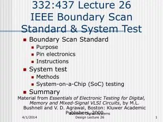
Why Boundary Scan Test? • The two main reasons that led in the mid-80s to the development of BST were: • The increasing complexity of integrated circuits (ICs) made it exceedingly difficult to develop test programs for the functional test of complex printed circuit boards (PCBs) • The shrinking effect of using small outline surface mount devices and advanced mounting technologies almost disabled physical access to internal PCB nodes and made in-circuit test exceedingly difficult
The application domain of BST • BST addresses the structural test of digital printed circuit boards • Keywords: structural, digital, PCBs • The narrow scope of BST contributed to its acceptance and to the quick development of products, but the potential of a standard embedded test infrastructure goes much beyond the initial application domain
The basic concept of BST • BS makes it possible to decouple the internal IC logic from the pins and allows “direct” access to any PCB node without backdriving effects
The Test Access Port (TAP) • TDI (Test Data Input): The serial data input to the BS register (a floating TDI is read as a 1) • TDO (Test Data Output): The serial data output of the BS register (in high-impedance except when a scan operation is in progress) • TCK (Test Clock): Clock for the test logic • TMS (Test Mode Select): A control input that defines the operating mode required for the test logic (a floating TMS is read as a 1)
The BS architecture • Besides the BS register, the test logic includes additional data registers, an instruction register and a TAP controller finite state machine
Access protocol to the BS architecture • The TAP controller places the instruction register in the TDI-TDO path • The proper bit sequence (instruction) is shifted in, setting the contents of the instruction register to select the required data register • The TAP controller places the selected data register in the TDI-TDO path • Test vectors may now be shifted in and out through the selected test data register
The basic BS cell • Three main operating modes: • Transparent • Controllability • Observability
BS: The basic test protocol • Shift in a new test vector (left mux in Shift mode, right mux in Normal or Test modes) • Apply the test vector (left mux in Shift or Capture modes, right mux in Test mode) • Capture the responses (left mux in Capture mode) • Shift out the responses (left mux in Shift mode)
Is BS test slow? • Scanning in and out each test vector / responses may be unacceptable for IC test, which may require hundreds of thousands of vectors • However, and considering the main application domain of BS (structural testing of PCBs), we shall see that the number of test vectors required is normally small
BS: The test data registers (1) • The BS register comprises the set of BS cells present in the circuit and is mandatory in any BS IC (at least two instructions selecting this register have to be supported: EXTEST and SAMPLE / PRELOAD) • The bypass register is mandatory and its function is to shorten the total length of the serial PCB-level chain (it has a single bit and is selected by the BYPASS instruction)
BS: The test data registers (2) • The identification register is optional and its function is to provide a 32-bit sequence enabling the test engineer to perform an identity check on each device supporting the IDCODE instruction • The user test data registers are also optional and will normally interface additional testability infrastructures introduced by the designers
The instruction register: Mandatory instructions (1) • The EXTEST instruction selects the BS register and imposes the (external) test mode in each BS cell, decoupling the IC core logic from the pins (the EXTEST instruction has a pre-defined code of all-0s) • The SAMPLE / PRELOAD instruction also selects the BS register, but the BS cells are now in transparent mode (this instruction does not have a pre-defined code)
The instruction register: Mandatory instructions (2) • Both EXTEST and SAMPLE / PRELOAD are used to test the board interconnects, but S/P is used to shift in the first test vector (why?) • The BYPASS instruction selects the bypass register and enables a 1-bit data path through those ICs which do not play a role in the current test operation (this instruction has an all-1 code and is automatically loaded into the instruction register on reset)
The TAP controller • The TAP controller is a small finite state machine that generates most of the control signals required by the BS architecture • The TAP controller commands the register placed between TDI and TDO to... • capture the logic value present at the parallel input of its cells • shift data serially through the register cells • update the cell parallel outputs with the values that were shifted in
The TAP controller states (1) • Capture, Shift and Update (-DR or -IR) are the states where the selected register performs the three main test operations • In the Test Logic Reset the BS register is in transparent mode and the functional logic operating normally • Run Test / Idle is used to perform certain test operations (such as BIST — Built-In Self-Test)
The TAP controller states (2) • Select, Exit1 and Exit2 (-DR or -IR) are temporary states • Exit1 and Exit2, combined with Pause (-DR or -IR) allow shifting of test data to be temporarily halted • The Select states allow selection of which type of register (-DR or -IR) to place between TDI and TDO
TAP controller timing details • State transitions occur with the rising edge in the TCK signal • Actions in a TAP controller state (such as capture, shift or update operations) occur with the falling edge of TCK in the state
BSDL: Boundary Scan Description Language • BSDL is a subset of VHDL that describes the BS infrastructure and its operation (approved as IEEE std. 1149.1b in 1994) • Mandatory features are not described in BSDL (e.g. a BSDL description does not describe the BYPASS register) • CAD tools making use of BSDL: testability analysis, automatic test pattern generation, fault diagnosis, etc.
HSDL: Hierarchical Scan DL and SVF: Serial Vector Format • HSDL complements BSDL, describing how IEEE 1149.1 is implemented at board level • SVF was jointly developed by Teradyne and Texas Instruments to enable a vendor-independent representation of IEEE 1149.1 test patterns • An SVF file contains ASCII statements consisting of commands and parameters of 3 types: state, offset and parallel commands
Case study: a simple BST infrastructure in a MACH210 • The objective is to design a very simple BST infrastructure around a core logic that implements the identity function
Required BST instructions • Only the three 1149.1 mandatory instructions are required:
TAP controller outputs • Control signals generated by the TAP controller: • BSUPD: Boundary scan update • INTRST: Internal reset • IRSHF: Instruction register shift, IRCAP: Instruction register capture, IRUPD: Instruction register update • DRSHF: Data register shift, DRCAP: Data register capture • MUXCTR: to select between data / instructions • TDOACT: TDO tristate control
BST register cells • “Free-running” clock configuration:
BP register cell (the latch stage is not required for this cell)
Design verification • What is the TAP state transition sequence shown?