Memory, Latches, & Registers
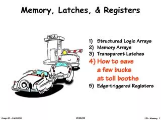
Memory, Latches, & Registers. Structured Logic Arrays Memory Arrays Transparent Latches How to save a few bucks at toll booths Edge-triggered Registers. General Table Lookup Synthesis. A. B. MUX Logic. Fn(A,B). Generalizing:

Memory, Latches, & Registers
E N D
Presentation Transcript
Memory, Latches, & Registers • Structured Logic Arrays • Memory Arrays • Transparent Latches • How to savea few bucksat toll booths • Edge-triggered Registers
General Table Lookup Synthesis A B MUX Logic Fn(A,B) Generalizing: Remember that, in theory, we can build any 1-output combinational logic block with multiplexers. For an N-input function we need a _____ input multiplexer. BIG Multiplexers? How about 10-input function? 20-input? 2N
I 0 0 I 0 1 I 1 0 I 1 1 A Mux’s Guts Decoder Selector Multiplexerscan be partitionedinto two sections. A DECODER thatidentifies thedesired input,and a SELECTOR that enables that inputonto the output. A 0 B A decodergeneratesall possibleproductterms fora set ofinputs A 1 Y B A 2 B A 3 B Hmmm, by sharing the decoder part of the logic MUXs could be adapted to make lookup tables with any number of outputs
A New Combinational Device D1 • DECODER: • k SELECT inputs, • N = 2k DATA OUTPUTs. • Selected Dj HIGH; all others LOW. D2 Have Imentionedthat HIGHis a synonym for ‘1’ andLOW meansthe sameas ‘0’ DN k NOW, we are well on our way to building a general purpose table-lookup device. We can build a 2-dimensional ARRAY of decoders and selectors as follows ...
There’s anextra levelof inversionthat isn’tnecessaryin the logic. However,it reducesthe capacitiveload on themodule drivingthis one. These are just “DeMorgan”ized NOR gates This ROM stores 16 bitsin 8 words of 2 bits. Shared Decoding Logic Decoder A B Cin 0 1 2 3 7 4 5 6 S Cout Configurable Selector We can build a general purpose “table-lookup” device calleda Read-Only Memory (ROM), from which we can implementany truth table and, thus, any combinational device Made from PREWIRED connections , and CONFIGURABLEconnections that can be either connected or not connected
Logic According to ROMs • ROMs ignore the structure of combinational functions ... • • Size, layout, and design are independent of function • • Any Truth table can be “programmed” by • minor reconfiguration: • - Metal layer (masked ROMs) • - Fuses (Field-programmable PROMs) • - Charge on floating gates (EPROMs) • ... etc. • Model: LOOK UP value of function in truth table... • Inputs: “ADDRESS” of a T.T. entry • ROM SIZE = # TT entries... • ... for an N-input boolean function, size = __________ 2N x #outputs
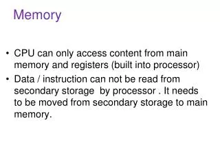
VREF Analog Storage: Using Capacitors We’ve chosen to encode information using voltages and we know from physics that we can “store” a voltage as “charge” on a capacitor: N-channel FET serves as an access switch Pros: w compact! Cons: w it leaks! refresh w complex interface w reading a bit, destroys it (you have to rewrite the value after each read) w it’s NOT a digital circuit word line bit line To write: Drive bit line, turn on access fet, force storage cap to new voltageTo read: precharge bit line, turn on access fet, detect (small) change in bit line voltage This storage circuit is the basis for commodity DRAMs
Here’s a feedback path,so it’s no longer acombinational circuit. “state” signal appears as both input and output G 0 0 1 1 D -- -- 0 1 QIN 0 1 -- -- QOUT 0 1 0 1 Q D G A “Digital” Storage Element It’s also easy to build a settable DIGITAL storage element (called a latch) using a MUX and FEEDBACK: A 0 Y Q stable B 1 Q follows D S
0 Q Q D 1 G=0 D G=0 Q 1 1 Looking Under the Covers • Let’s take a quick look at the equivalent circuit for our MUX when the gate is LOW (the feedback path is active) Advantages: 1) Maintains remembered state for as long as power is applied. 2) State is DIGITAL Disadvantage: 1) Requires more transistors This storage circuit is the basis for commodity SRAMs
Not affected by noise Waveform for inverter pair Feedback constraint: VIN = VOUT VOUT Three solutions: w two end-points are stable w middle point is unstable VIN We’ll get back to this! Why Does Feedback = Storage? BIG IDEA: use positive feedback to maintain storage indefinitely. Our logic gates are built to restore marginal signal levels, so noise shouldn’t be a problem! Result: a bistable storage element VOUT VIN
D D Q Q G G 1 Q D 0 G Static D Latch Positive latch Negative latch What is thedifference? Q follows D D G Q Q stable “static” means latch will hold data (i.e., value of Q) while G is inactive, however long that may be.
>tPULSE >tSETUP >tHOLD • tPULSE: minimum pulse width • guarantee G is active for long enough for latch to capture data • tSETUP: setup time • guarantee that D value has propagated through feedback path before latch closes • tHOLD: hold time • guarantee latch is closed and Q is stable before allowing D to change A DYNAMIC Discipline Design of sequential circuits MUST guarantee that inputs to sequential devices are valid and stable during periods when they may influence state changes. This is assured with additional timing specifications. G D
Flakey Control Systems Here’s a strategy for saving 2 bucks the next time you find yourself at a toll booth!
Flakey Control Systems Here’s a strategy for saving 2 bucks the next time you find yourself at a toll booth!
Flakey Control Systems Here’s a strategy for saving 2 bucks the next time you find yourself at a toll booth! WARNING: Professional Drivers Used! DON’T try this At home!
Escapement Strategy The Solution: Add two gates and only open one at a time.
Escapement Strategy The Solution: Add two gates and only open one at a time.
Escapement Strategy The Solution: Add two gates and only open one at a time.
Escapement Strategy The Solution: Add two gates and only open one at a time. (Psst… Don’t tell the toll folks)
Escapement Strategy The Solution: Add two gates and only open one at a time. (Psst… Don’t tell the toll folks)
Escapement Strategy The Solution: Add two gates and only open one at a time. (Psst… Don’t tell the toll folks)
Escapement Strategy The Solution: Add two gates and only open one at a time. (Psst… Don’t tell the toll folks)
Escapement Strategy The Solution: Add two gates and only open one at a time.
Escapement Strategy The Solution: Add two gates and only open one at a time.
Escapement Strategy The Solution: Add two gates and only open one at a time. (Psst… Don’t tell the toll folks)
Escapement Strategy The Solution: Add two gates and only open one at a time. (Psst… Don’t tell the toll folks)
Escapement Strategy The Solution: Add two gates and only open one at a time. (Psst… Don’t tell the toll folks)
Escapement Strategy The Solution: Add two gates and only open one at a time. (Psst… Don’t tell the toll folks)
Escapement Strategy The Solution: Add two gates and only open one at a time.
Escapement Strategy The Solution: Add two gates and only open one at a time.
Escapement Strategy The Solution: Add two gates and only open one at a time. (Psst… Don’t tell the toll folks) KEY: At no time is there an open path through both gates…
D Q D Q D Q G G Edge-triggered Flip Floplogical “escapement” D Q D Q master slave CLK CLK • Observations: • only one latch “transparent” at any time: • master closed when slave is open (CLK is high) • slave closed when master is open (CLK is low) • no combinational path through flip flop • w Q only changes shortly after 0 1 transition of CLK, so flip flop appears to be “triggered” by rising edge of CLK Transitions mark instants, not intervals
D Q D Q D Q G G Flip Flop Waveforms D Q D Q master slave CLK CLK D CLK Q master closed slave open slave closed master open
D Q D Q G G Two Issues D Q master slave CLK • Must allow time for the input’s value to propagate to the Master’s output while CLK is LOW. • This is called “SET-UP” time • Must keep the input stable, just after CLK transitions to HIGH. This is insurance in case the SLAVE’s gate opens just before the MASTER’s gate closes. • This is called “HOLD-TIME” • Can be zero (or even negative!) • Assuring “set-up” and “hold” times is what limits a computer’s performance
<tPD >tSETUP >tHOLD • tSETUP: setup time • guarantee that D has propagated through feedback path before master closes D Q • tHOLD: hold time • guarantee master is closed and data is stable before allowing D to change Flip-Flop Timing Specs D Q Q CLK CLK D tPD: maximum propagation delay, CLK Q
Summary • • Regular Arrays can be used to implement arbitrary logic functions • ROMs decode every input combination (fixed-AND array) and compute the output for it (customized-OR array) • PLAs decode an minimal set of input combinations (both AND and OR arrays customized) • • Memories • ROMs are HARDWIRED memories • RAMs include storage elements at each WORD-line and BIT-line intersection • dynamic memory: compact, only reliable short-term • static memory: controlled use of positive feedback • • Level-sensitive D-latches for static storage • • Dynamic discipline (setup and hold times)