Download
1 / 32
330 likes | 515 Vues
Modelling of miniature proton exchange membrane fuel cells for portable applications. J.O. Schumacher 1 , E. Fontes 3 , D. Gerteisen 1 , F. Goldsmith 1 , R. Klöfkorn 2 , A. Hakenjos 1 , K. Kühn 1 , M. Ohlberger 2 , A.Schmitz 1 , K. Tüber 1 , C. Ziegler 1

E N D
Modelling of miniature proton exchange membrane fuel cells for portable applications • J.O. Schumacher1, E. Fontes3, D. Gerteisen1, F. Goldsmith1, R. Klöfkorn2, A. Hakenjos1, K. Kühn1, M. Ohlberger2, A.Schmitz1, K. Tüber1, C. Ziegler1 • 1. Fraunhofer Institute for Solar Energy Systems, Heidenhofstr. 2, 79110 Freiburg, schum@ise.fhg.de, Germany • 2. Institute of Applied Mathematics, University of Freiburg, Herrmann-Herder-Str. 10, 79104 Freiburg, Germany • 3. COMSOL AB, Tegnergatan 23, SE-111 40 Stockholm, Sweden
Overview • Examples of portable fuel cell systems • Model based analysis of impedance spectra • Modelling of self-breathing fuel cells • Characterisation of an along-the-channel fuel cell • Dynamic simulation of two-phase flow • Conclusion and outlook
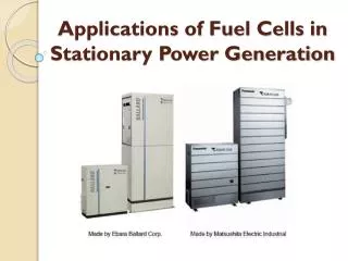
Fuel cell system for a professional broadcast camera • Completely integrated system with 4 fuel cell stacks • 40 W average system power • 2 Metal Hydride Storages (100 Nl H2 or 150 Whel) • Integrated DC/DC- Converter • Miniature fans for air supply
Mobile power box • Portable power supply • Power: max. 100 W average 50 W • Metal Hydride Storage • Control based on micro processor • 12 V voltage supply with DC/DC- Converter
Electrode agglomerate model • Electrode is assumed to be made of porous spherical catalyst grains • Oxygen is dissolved at the outer surface of the agglomerate • Diffusion of dissolved oxygen in the grain and the film in radial direction • Local current density is given by the Tafel-equation Graph: Jaouen et al., 2002
Cathode agglomerate model Mass balance Charge balance Oxygen flux in agglomerate
Cathode agglomerate model Charge balance Ohm`s law
Comparision of measured and simulated polarisation curves Small current density: change of Tafel-slope Influence of surface-to-volume ratio L of agglomerates L = 6 105 m-1 L = 9 104 m-1 cell potential / [V] cell potential / [V] current density / [A/m2] current density / [A/m2]
Simulation of impedance spectra • Perturbation of solution variables of PDEs • Small perturbations: linearise and Laplace-transform PDEs • Calculate impedance: Resistance [Wm2] Resistance [Wm2]
Comparision of measured and simulated impedance spectra • Minimum value of the radius of the impedance arc is reached at a current density of 260mA/cm2. • Mass transport limitation is observed for higher current density: increase of radius of impedance arc. current density [A/m2] meas sim
Influence of double layer capacitance on impedance spectra Double layer capacitance CDL = 3 107 F m-3 Small double layer capacitance: Two seperate semicircles appear GDL current density [A/m2] current density [A/m2] Influence of electrode
Planar and self-breathing fuel cells based on printed circuit board technology • Benefits of technology: • Small cell thickness • High mechanical strength • Low cost components • Well known printed circuit board production technology • Integration of electronic circuits
Modelling domain and assumptions • Two dimensional model • Plug flow conditions in anodic gas channel • Convective flux of species through membrane and on cathode side neglected • No phase transition accounted for
Discretisation mesh and governing equations • Multicomponent diffusion of gas species: Stefan-Maxwell equation • Electronic and protonic potential: Poisson equation • Transport of water across membrane: modified Stefan-Maxwell equation • Temperature distribution: heat equation • l
Hydrogen and oxygen distribution H2 molar fraction O2 molar fraction anode cathode Arrows: total flux of hydrogen and oxygen. Vcell = 0.4 V
Water distribution and flux H2O molar fraction x 10-3 H2O molar fraction anode cathode Arrows: total flux of water. Vcell = 0.4 V
Heat flux and temperature T [K] anode cathode • Arrows: total flux of heat. • Cooling effect of ribs. • Vcell = 0.4 V
Electronic and protonic potential, current direction Protonic potential Electronic potential fe [V] fp [V] Arrows indicate the technical current direction.
Comparison of Experiment and Simulation Experiment Simulation • Opening ratio = cathode opening width / current collector rib width. • Limiting current is determined by oxygen supply through cathode opening.
Current distribution in cathode gas diffusion layer cathode electrode cut line (e) GDL (e) membrane (e) Normalised x-coordinate Normalised y-coordinate
PEM fuel cell model based on FLUENT CFD-software • Submodels: • The electrochemical submodel predicts the local current-to-voltage relation in the MEA. • The electrical submodel accounts for electron flow and ohmic heat generation. • The MEA submodel describes transport of water and ions through a Nafion membrane.
Segmented fuel cell ‚Along - the - Channel‘ • Flow-field geometry: • Parallel channels • Determination of • spatially resolved • current density • Measured values: • temperature, • gas flow-rates, • relative humidity
Current distribution along the channel • Comparison of measurement (dots) and simulation (lines) • Variation of air flow rate on the cathode side • All model parameters are kept constant except air flow and average current gas flow direction:
Analysis Relative humidity of air in the channel Temperature of air in the channel Relative humidity of air at MEA Membrane protonic resistivity
Profiles of flow velocity and temperature including inlet region velocity profile temperature profile
Dynamic simulation of two phase flow Modelling concept by Mario Ohlberger (Institute for Applied Mathematics, Freiburg). Solution of the PDEs for: • Two phase flow in porous media • Species transport in the gas phase • Energy balance in the porous media • Potential flow of electrons and protons Adaptive grid generation in space / time Colours: pressure distribution for counter-flow case. Problem: Determination of material parameters
Two-phase flow in porous gas diffusion layer and electrodes phase-transition Mass balance Darcy-law Water and gas saturation Capillary pressure
Simulation examples Wasser-dampf flüssigesWasser H2 O2 Mass fraction of gas components and saturation of liquid water Colors: Red: 1, Blue: 0
Conclusion Agglomerate model • The agglomerate model reproduces both, measured polarisation curves and impedance spectra. • Change of active agglomerate surface-to-volume ratio depending on the operation point? Planar fuel cells • Our two-dimensional one-phase model includes all relevant processes of planar fuel cells: gas transport, heat transport, electrochemical reaction. • The model serves as a design tool for self-breathing planar fuel cells.
Conclusion Current distribution • We validated the CDF model with locally distributed current measurements. • The CFD model agrees to measurement results if the cell is operated in the one-phase regime. • We are working on a dynamic two-phase flow model taking into account liquid water transport in porous media. • The model is extended to 3D. Parallel computing and adaptive grid generation is utilised. Two-phase flow