Fuel Cells in Portable Systems
170 likes | 361 Vues
Fuel Cells in Portable Systems. Nicholas Benavides University of Illinois at Urbana-Champaign. This work supported by Army Research Office, National Science Foundation, and Grainger CEME. Outline. Motivation Direct methanol fuel cells Power conversion requirements

Fuel Cells in Portable Systems
E N D
Presentation Transcript
Fuel Cells in Portable Systems Nicholas Benavides University of Illinois at Urbana-Champaign This work supported by Army Research Office, National Science Foundation, and Grainger CEME Grainger Center for Electric Machinery and Electromechanics
Outline • Motivation • Direct methanol fuel cells • Power conversion requirements • Optimization efforts at Illinois • Conclusion Grainger Center for Electric Machinery and Electromechanics
Motivation • In portable power applications such as laptop computers and communication equipment, batteries are quickly becoming the largest, heaviest component. • The best Li-Ion battery technology has a specific energy density of <500 W·hr/kg. • PEM fuel cells promise >1000 W·hr/kg • In lightweight, portable energy sources, the design goal is minimization of the total system mass. • High-efficiency converters are heavy but less fuel is needed. Reference: NRC “Meeting the energy needs of future warriors” 2004 Grainger Center for Electric Machinery and Electromechanics
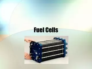
Direct methanol fuel cells (DMFC) Grainger Center for Electric Machinery and Electromechanics
DMFC fuel cell limitations • Fuel / oxidant starvation can cause hydrolysis at the electrodes, which burns the platinum catalyst. • System has slow response due to thermal and mechanical (fluid) time constants • Membranes are fragile (dehydration and contamination) • Complicated system of pumps and blowers required • Bipolar plates are expensive to manufacture • System creates humid exhaust Grainger Center for Electric Machinery and Electromechanics
Laminar flow fuel cells (LFFC) • Project began as a collaboration with INI Power Systems and SmartSpark Energy Systems Grainger Center for Electric Machinery and Electromechanics
Power conversion requirements • Nominal fuel cell operating point requires a delicate balance of thermal equilibrium, power output, fuel consumption, and water management issues. • Fuel cells operate best with controlled electrical current draw. • Output voltage of single cells is low (<1 V), and large stacks can reduce efficiency. • Dc-dc conversion and a secondary energy storage device such as a battery is required. Grainger Center for Electric Machinery and Electromechanics
Fuel cell electrical characteristics • Maximum efficiency is typically not maximum power operating point. • “Voltage efficiency” includes activation, ohmic conduction, and mass transport losses. • “Current efficiency” includes fuel crossover and corrosion current. Grainger Center for Electric Machinery and Electromechanics
Fuel cell / battery hybrid with boost converter • Battery establishes output voltage, and allows fuel cell stack to operate at an arbitrary power level. Grainger Center for Electric Machinery and Electromechanics
Optimal converter design • Previous dc-dc converter optimization efforts have focused on minimum weight with constrained efficiency, or maximum efficiency with constrained weight. Neither approach addresses the proper metric. • High efficiency = Heavy converter but less fuel needed • Due to converter power loss: • Extra mass = Extra fuel + Added fuel cell mass • Extra fuel depends on mission duration Grainger Center for Electric Machinery and Electromechanics
Converter modeling • The usefulness of optimal design depends on the accuracy of the underlying mathematical models. • The loss mechanisms have been modeled with state of the art static loss models, exclusively drawing on information available before the design, such as datasheets. • The free optimization variables were chosen to allow simple physical constraints: • Inductor current ripple • Winding current density • Winding fill factor • Switching frequency • Peak magnetic flux in the core • Output capacitance • MOSFET On-state Resistance Grainger Center for Electric Machinery and Electromechanics
Experimental setup • An experimental test converter was run with varying conditions: • 3 different inductors • 100, 200, 400, and 1000 kHz • 1, 2, 3, and 4 A input current • High efficiency converters make power loss very difficult to measure. At 96% efficiency, 0.15% accuracy in the current measurements leads to 7.5% uncertainty in power loss. Experimental 30 W boost converter Grainger Center for Electric Machinery and Electromechanics
Experimental results • Mid-sized inductor (41.1 μH) test results • Considerable error at highest frequency • Mean error: 6.8% Standard deviation: 6.7% Grainger Center for Electric Machinery and Electromechanics
Optimization results • Optimal efficiency increases with mission duration • Design variables change constraints Grainger Center for Electric Machinery and Electromechanics
Comparison to available converter • Mission duration of 100 hours and FC efficiency of 40% and an incremental fuel cell mass of 25 g/W • Texas Instruments PT5041 with output of 12 W @ 12 V, has a power density of 1.8 W/g and a full load efficiency of 90% • At 30 W, this would scale to 17 g of converter, 75 g of extra fuel cell mass, and 125 g of extra fuel. Total = 217 g. • Optimal design at 100 hours led to 8 g of converter, 14 g of extra fuel cell mass, and 59 g of extra fuel. Total = 81 g. • Even if controller and other components add to the mass of the converter, over 100 g of savings will still be achieved. Grainger Center for Electric Machinery and Electromechanics
Conclusions • Optimal converter efficiency does not necessarily lead to a minimum mass system. • The trade-off between mass and efficiency is affected by nominal mission duration. • All models must use information readily available to designers. • The general methodology can be adapted to accommodate other converter topologies, and new loss models. Grainger Center for Electric Machinery and Electromechanics