
Elementary Two-Pole Motor
E N D
Presentation Transcript
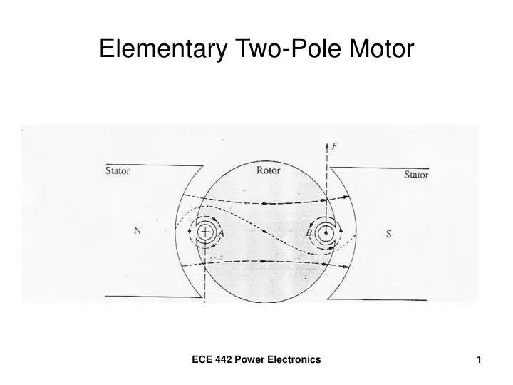
Elementary Two-Pole Motor ECE 442 Power Electronics
Elementary Two-Pole Generator ECE 442 Power Electronics
Voltage induced in the coil, e • Flux through the coil window is sinusoidal • Φ= Φmaxsin(ωt) • Voltage induced in coil,e • e = N(dΦ/dt) • e = NωΦmaxcos(ωt) • Emax = ωNΦmax • Emax = 2πfNΦmax • Erms = 4.44fNΦmax ECE 442 Power Electronics
Directions of induced voltage and current • Develop CCW counter-torque • “Bunching” must occur at the top of coil side B and the bottom of coil side A • Coil current is CCW as viewed from south pole ECE 442 Power Electronics
Basic DC Generator Separately Excited Shunt Generator ECE 442 Power Electronics
Generator Action • Permanent-magnet field • One-turn armature • Drive so that Ea>Ebat • Current Ia flows to charge Ebat ECE 442 Power Electronics
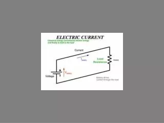
From a Circuit Point-of-View • “Generate” voltage Ea • When supplying current, the machine develops a “counter-torque” in opposition to the driving torque ECE 442 Power Electronics
Motor Action • “Uncouple” the Prime Mover • Eventually, Ea will decrease so that Ea<Ebat • Ia flows as shown • Armature turns in the same direction ECE 442 Power Electronics
From a Circuit Point-Of-View • Counter-emf, Ea, is induced, opposing the driving voltage Ebat • Machine develops a driving torque ECE 442 Power Electronics