Download
1 / 12
140 likes | 463 Vues
A Compound Reconfigurable Microstrip Parasitic Array. Mentee: Jacob Block Mentor: Jake Adams. Why Compound Reconfigurable?. Reconfigurable antenna properties can be changed dynamically by external control Compound reconfigurability Multiple Radiation Patterns

E N D
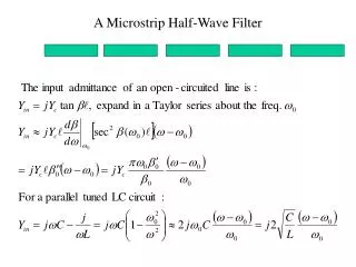
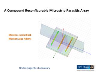
A Compound Reconfigurable Microstrip Parasitic Array Mentee: Jacob Block Mentor: Jake Adams
Why Compound Reconfigurable? • Reconfigurable antenna properties can be changed dynamically by external control • Compound reconfigurability • Multiple Radiation Patterns • Receive signals from multiple directions • Multiple Operating Frequencies • Antennas are designed for specific operating frequencies • WiMAX (3.5 GHz) • WiFi (2.4 GHz) M. Slater, “A compound reconfigurable antenna,” M.S. thesis, University of Illinois, Urbana, IL, 2008.
Microstrip Parasitic Array • Antenna (substrate, ground, patch) • Switches on parasitic elements change pattern/frequency M. Slater, “A compound reconfigurable antenna,” M.S. thesis, University of Illinois, Urbana, IL, 2008.
Radiation Patterns • Yagi-Uda Antenna (dipole cylinders) • Directional radiation pattern Length of Reflector > Length of Driven > Length of Directors
Operating Frequency of Antenna • Frequency Dependent • Length of arms • Switches • Varactor (variable capacitor) • Spacing between arms • Averaging Yagi-Uda Rules of Thumb (Numerical, not Analytic)
3.5Ghz – Right Tilt 2.4Ghz – Right Tilt 1 pF 10 pF 1 pF 10 pF varactors
New Design – Reduce Size, Reduce Averaging, Increase Performance • Ground Plane Resonators (slits into the ground plane) • New switching topology • Eliminate Varactors • Simplify DC bias network (less cables) • Less averaging Mustache Meander line
New Switching Topology 3.5Ghz – Right Tilt 2.4Ghz – Right Tilt
Conclusion • What I learned • HFSS • Antennas • Thanks PURE! • Thanks Jake! • Questions? THANKS!