Download
1 / 40
400 likes | 428 Vues
Discussion on optimizing the ILC vertex detector design for physics with focus on quark charge measurements, software tools, and performance evaluation. Importance of vertex charge reconstruction and charge dipole procedure explored.

E N D
Elementary Particle Physics Seminar Oxford, 6 November 2007 ILC vertex detector R&D: optimising the detector design for physics Sonja Hillert (Oxford)
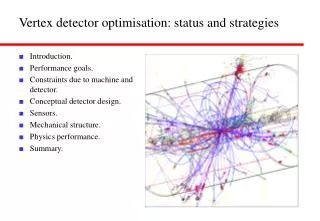
Outline of this talk • Role of the vertex detector for extracting ILC physics • Measuring quark charge: vertex charge and charge dipole procedure • Sensitivity of vertex charge reconstruction to detector design: fast MC results • LCFI Vertex Package: software tools for full MC studies • Optimising the vertex detector design • Recent results of LCFI vertex detector R&D on sensors & mechanical support
first order jet finding flavour identification reconstruction of tracks, CAL-cells energy flow objects b charged B bbar classify B as charged or neutral charge dipole, protons, charged kaons or leptons from SV, TV tune track-jet association for tracks from SV or TV contained in neighbouring jet b b-jets neutral B bbar classify D as charged or neutral c charged D c-jets cbar charged kaons or leptons neutral D c uds-jets cbar associate with parent jet in some cases gluon-jets Typical event processing at the ILC
M. Battaglia Dependence of physics reach on detector performance • Flavour tag needed for event selection and reduction of combinatoric backgrounds • Quark charge sign determination used for measurement of ALR, • angular correlations ( top polarisation) – vertex detector performance crucial • Examples: • Higgs branching ratios: • classical example of a process • relying on flavour tag • e+e- ZHH: • 4 b-jets in final state requiring • excellent tagging performance; • could profit from quark charge • sign selection
Sensitivity to deviations of extra-dimensions model from SM predicition (S. Riemann): without quark sign selection with perfect quark sign selection Processes requiring quark sign selection: e+e- b bbar • e+e- bb: indirect sensitivity to new physics, such as extra spatial dimensions, leptoquarks, • Z´, R-parity violating scalar particles (Riemann, LC-TH-2001-007, Hewett PRL 82 (1999) 4765); quark charge sign selection to large cos q needed to unfold cross section and measure ALR:
s e.g.c q’ q’ b W+ t e+ e- t W b q q e.g. s c a typical e+e- t t event Processes requiring quark sign selection: e+e- t tbar • e+e- tt demanding for vertex detector: • multijet event: final state likely to include soft jets • some of which at large polar angle • flavour tag needed to reconstruct the W bosons and top-quarks • quark charge sign selection will help to reduce • combinatoric backgrounds • top decays before it can hadronise: polarisation of top quark • can be measured from polarisation of its decay products; • best measured from angular distribution of s-jet (quark charge)
Requirements • To measure quark charge efficiently one needs: • an excellent vertex detector: • pixel-based system • few micron point resolution (< 5 mm) • small inner layer radius (~ 15 mm) • good polar angle coverage • low mass support structure (<= 0.1 % X0) • mechanical stability • appropriate high-level reconstruction software, e.g.: • topological vertex finding • flavour tagging • vertex charge reconstruction (charged hadrons) • charge dipole reconstruction (neutral B hadrons)
Vertex charge reconstruction • b-jets contain a complex decay chain, from which the charge has to be found • in the 40% of cases where b quark hadronises to charged B-hadron, • quark sign can be determined by vertex charge • need to find all stable tracks from • B decay chain: • define seed axis • cut on L/D (normalised distance • between IP and projection of track POCA • onto seed axis) • tracks that form vertices other than IP • are assigned regardless of their L/D • need vertex finding as prerequisite (definition of seed axis) • in most analyses, only calculate charge for jet of specific flavour: need flavour tagging • probability of mis-reconstructing vertex charge is small for both charged and neutral cases
SLD, NIM A 447 (2000) 90-99 Charge dipole procedure • For some neutral vertices, quark charge can be obtained from • the charge dipole formed by B- and D-decay vertex. • “ghost track” vertexing algorithm (aka ZVKIN) • developed at SLD, was shown to yield higher purity for • charge dipole than standard ZVTOP code (ZVRES, cf p12) • advantage: one-prong vertices identified by vertex finder • increased efficiency, especially at short B decay lengths • at ILC, charge dipole procedure still to be explored
Performance of charge reconstruction: leakage rates • define leakage rate l0 as probability of reconstructing neutral hadron as charged • performance strongly depends on low momentum tracks: • largest sensitivity to detector design for low jet energy, large cos q preliminary results from fast MC study (SGV)
250 mm 60 mm 25 mm 15 mm 8 mm e+e- BEAM 100 mm Using vertex charge for detector optimisation • Using fast MC SGV, studied dependence of leakage rate on vertex detector design: • compared detectors with different inner layer radii ( beam pipe radii) • varied amount of material per detector layer (factor 4 compared to baseline) • translated into integrated luminosityrequired to obtain physics results of same significance • for processes requiring independent quark charge measurement in 2 jets, • increase of beam pipe from 15 to 25 mm has sizeable effect (factor 1.5 – 2) preliminary results from fast MC study (SGV)
The LCFI Vertex Package • The LCFIVertex package provides, in a full MC and reconstruction framework: • vertex finder ZVTOP with branches ZVRES and ZVKIN (new in ILC environment) • flavour tagging based on neural net approach (algorithm: R. Hawkings, LC-PHSM-2000-021); includes full neural net package; flexible to allow change of inputs, network architecture • quark charge determination, currently only for jets with a charged ‘heavy flavour hadron’ • first version of the code released end of April 2007: • code, default flavour tag networks and documentation available from the ILC software portal • http://www-flc.desy.de/ilcsoft/ilcsoftware/LCFIVertex • next version planned to be released this Friday: • minor corrections, e.g. to vertex charge algorithm; further documentation • diagnostic features to check inputs and outputs • new vertex fitter based on Kalman filter to improve run-time performance
central for flavour tag: • pT-corrected vertex mass • this kinematic correction is applied • to partly account for undetected • neutral particles ZVTOP vertex finder, Pt-corrected mass • two branches: ZVRES and ZVKIN (already mentioned when discussing charge dipole) • The ZVRES algorithm (D. Jackson, NIM A 388 (1997) 247) • very general algorithm that can cope with arbitrary multi-prong decay topologies • ‘vertex function‘ calculated from Gaussian ´probability tubes´ representing tracks • iteratively search 3D-space for maxima of this function and minimise c2 of vertex fit
b c uds Flavour tagging approach • Vertex package provides flavour tag procedure developed by R. Hawkings et al • (LC-PHSM-2000-021) as default • number of vertices found determines which • NN input variables are used: • if secondary vertex found: MPt , momentum of secondary vertex, and its decay length and decay length significance • if only primary vertex found: momentum and impact parameter significance in R-f and z for the two most-significant tracks in the jet • in both cases: joint probability in R-f and z (estimator of • probability for all tracks to originate from primary vertex) • flexible: permits user to change input variables, architecture and training algorithm of NN
b c (b-bkgr) b c b c (b-bkgr) c c (b-bkgr) c c (b-bkgr) open: BRAHMS, LC-note full: MARLIN (Mokka), Si-only track cheater c open: SGV fast MC full: MARLIN, SGV-input open: SGV fast MC full: MARLIN, SGV-input b open: BRAHMS, LC-note full: MARLIN (Mokka), Si-only track cheater Identical input events Identical input events Flavour tagging performance Z-peak Z-peak 500 GeV 500 GeV
Diagnostic features • plan to make available inputs and outputs for ZVRES & flavour tag (later: vertex charge) • nearly complete: LCFIAIDAPlot – module for flavour tag diagnostics based on AIDA • input and output variables of the flavour tag neural nets, separately for b-, c-, light jets • graphs of purity vs efficiency and flavour leakage rates (i.e. efficiencies of wrong flavours) vs efficiency separately for the 1-, 2- and 3-vertex case • JAS3-macro to plot these easily • optionally: raw numbers of jets vs NN-output, AIDA tuple with flavour tag inputs written out example: inputs to flavour tag
New vertex fitter: Kalman filter • Motivation: improve run time performance by replacing the “space-holder” • Least-Squares-Minimisation (LSM) fitter of first release • Kalman filter code by S. Gorbunov, I. Kisel interfaced to Vertex Package • successfully tested: • find same flavour tagging performance • as with LSM-fitter • resulting improvement in run time performance: • overall run time of Vertex Package is • reduced to ~ 25% of the 1st-release value
Towards a realistic simulation • Current simulations are based on many approximations / oversimplifications. • The resulting error on performance is at present unknown and could be sizable, • especially when looking at particular regions in jet energy, polar angle (forward region!) • Issues to improve: • Vertex detector model: replace model with cylindrical layers by model with barrel staves • GEANT4: switched off photon conversions for time being (straightforward to correct) • hit reconstruction: using simple Gaussian smearing at present; realistic code exists only for DEPFET sensor technology, not for CPCCDs and ISIS sensors developed by LCFI • track selection: • KS and L decay tracks suppressed using MC information • tracks from hadronic interactions in the detector material discarded using MC info – only works for detector model LDC01Sc (used for code validation) at present • current default parameters of the code optimised with fast MC or old BRAHMS (GEANT3) code • default flavour tag networks were trained with fast MC
c (b-bkgr) full LDCtracking Z-peak c b b open: VXD geometry with ladders full: VXD geometry with cylinders c (b-bkgr) c (b-bkgr) c track cheater, Z-peak b track cheater (04/07) 500 GeV open: photon conversions, uncorrected full: photon conversions off open: hadronic interaction effects full: no hadronic interactions Examples of impact of simplifications • effects of simplifications can be sizeable; • note: photon conversions and hadronic • interactions in detector material can • efficiently be corrected for • currently making initial checks needed for • implementing these corrections c
Further development of the Vertex Package • Areas of relevance for wider user community: • integration into ALCPG software framework org.lcsim: drivers under development in the US, • to be released as soon as possible (N. Graf) • consistent IP treatment, based on per-event-fit in z and on average over N events in Rf • Vertexing: • explore use of ZVKIN branch of ZVTOP for flavour tag and quark charge determination: • optimise parameters • study performance at the Z-peak and at sqrt(s) = 500 GeV • explore how best to combine output with that of ZVRES branch for flavour tag • use charge dipole procedure (based on ZVKIN) to study quark charge determination for (subset of) neutral hadrons
Improvements and extensions • Areas of relevance for wider user community contd: • Flavour tagging: explore ways to improve the tagging algorithm, e.g. through use of • different input variables and/or different set-up of neural nets that combine these • improvements to MPt calculation using calorimeter information, e.g. from high-energy p0 • vary network architecture (number of layers & nodes, node transfer function), training algorithm • explore new “data mining” and classification approaches (e.g. decision trees, … ) • Vertex charge reconstruction: • revisit reconstruction algorithm using full MC and reconstruction (optimised with fast MC) • Functionality specifically needed for vertex detector optimisation: • Correction procedure for misalignment of the detector and of the sensors will need to be • developed, adapted or interfaced (see optimisation of the detector)
Optimising the detector design • Simulations serve to estimate performance of • benchmark quantities: impact parameter resolution, flavour tag, vertex charge reconstruction • reconstruction of physics quantities obtained from study of benchmark physics processes • Vertex detector-related software cannot be developed in isolation: • vertexing, flavour tag, vertex charge rec´n performed on a jet-by-jet basis (depends onjet finder) • strong dependence on quality of input tracks (i.e. hit and track reconstruction software) • physics processes to optimise calorimeter also depend on tagging performance (e.g. ZHH) • Study of benchmark physics processes • performed in close collaboration with the two main ILC detector concept study groups: SiD and ILD (formerly GLD / LDC) • ILCSC has issued call for Letters of Intent, to be submitted 1 October 2008 • These will be followed by more detailed Engineering Design Studies to be completed by 2010
Benchmark Physics Studies • Benchmark physics processes should be typical of ILC physics and sensitive to detector design. • A Physics Benchmark Panel comprising ILC theorists and experimentalists has published • a list of recommended processes that will form the baseline for the selection of processes • to be studied in the LoI- and engineering design phases. • Following processes were highlighted as most relevant by the experts (hep-ex/0603010): particularly sensitive to vertex detector design
Parameters and aspects of design to be optimised • The Vertex Package, embedded into full MC and reconstruction frameworks, • permits the following aspects of the vertex detector design to be optimised: • Beam pipe radius • Sensor thickness, material amount at the ends of the barrel staves • Material amount and type of mechanical support (e.g. RVC, Silicon carbide foams) • Overlap of sensors: linked to sensor alignment, tolerances for sensor positions along the beam & perpendicular to it • Arrangement of barrel staves • Long barrel vs short barrel plus endcap geometry • Study of trade-offs, involving variations of more than one parameter, should be aimed at • Physics simulation results will be only one of the inputs that determine the detector • design – the more decisive input may well be provided by what is technically feasible.
LCFI sensor development: introduction • LCFI pursuing development of two sensor technologies for ILC vertex detector: • Column Parallel CCD (CPCCD) • CPC1 (first CPCCD) • CPC2 – second generation, large area device • In-situ Storage Image Sensor (ISIS) • proof-of-principle device (ISIS1) • effort towards ISIS2 CPC1 CPC2 ISIS1
M M N N “Classic CCD” Readout time NM/fout Column Parallel CCD Readout time = N/fout Column Parallel CCD: principle • Main sensor technology developed by LCFI • Every column has its own amplifier and ADC • Readout time shortened by ~3 orders of magnitude compared to “classic” CCD • All of the image area is clocked, complicated by the large gate capacitance • Optimised for low voltage clocks to reduce power dissipation
CPC2 devices ISIS1 Busline-free CPC2 CPC2-70 104 mm CPC2-40 CPC2-10 • Three device sizes: 10, 40 and 70 mm length (requirement for inner layer device: 100 mm) • Some devices designed to reach high speed (up to 50 MHz operation): • 2-level metallisation permits using whole image area as distributed bus line • Charge to voltage conversion can happen on CCD (50% channels) or on readout chip (other 50%)
CPC2 test results 20 MHz System noise = 110 e- RMS 10 MHz System noise = 75 e- RMS • short (CPC2-10) device, high-speed design, tested with 55Fe signal(1620 e-, MIP-like) • X-ray hits seen up to 45 MHz: important milestone • CPC2 works with clock amplitude down to 1.35 Vpp • in standalone tests (w/o readout chip, using 2-stage source follower outputs): at 10 MHz achieve noise level of 75 e- RMS (CMOS driver chip) • tests continuing
Readout chips: CPR1 and CPR2 Voltage and charge amplifiers 125 channels each Analogue test I/O Digital test I/O 5-bit flash ADCs on 20 μm pitch Cluster finding logic (22 kernel) Sparse readout circuitry FIFO Bump bond pads CPR1 CPR2 • both chips made on 0.25 μm CMOS process (IBM) • front-end amplifiers matched to the CCD outputs • additional test features in CPR2 • CPR2 includes data sparsification Wire/Bump bond pads
Cluster finding with X-ray signals Sparsified output Readout chips: results CPR1, 1 MHz: CPR2: sparsification Voltage outputs • non-inverting (negative signals) Charge outputs • inverting (positive signals) • CPR1: in charge channels expected gain observed, constant over device; • in voltage channels gain drops from edge to the centre of the device (not understood) • CPR2: same gain drop in voltage channels as in CPR1, charge channels don’t work; • errors in sparsification for cluster distances < 60 – 100 pixels: extensive tests with measured • and simulated input led to major re-design of next generation chip CPR2A
Clock driver for CPCCD • Challenge: providing 2 Vpp clocks at 50 MHz for • CPCCD (capacitance 40 nF / phase): 20 A peak current • Further requirements: • low power dissipation • must be close to CCD (to reduce parasitic inductance) • must not add too much to material budget • may have to work at low temperature (down to -100 oC) • 2 approaches: transformer (fallback), custom ASIC (baseline) • performed tests with 16:1 transformer integrated into PCB (above) • and with first version of driver chip CPD1 (right): • 1 chip drives 2 phases, up to 3.3 V clock swing • 0.35 mm CMOS process, chip size 3 x 8 mm2 • 8 independent clock sections • careful layout on- and off-chip to cancel inductance • bump-bondable
CPD1 CPC2-40 CPR2 Integration of CPC, CPR and CPD • a lot more work needed to arrive at ladders • (design of ladder end: left) • but an integrated system of CPC, CPR and CPD • exists and works up to frequency of 9 MHz • (speed limited by CPR2)
LCFI Mechanical Studies • LCFI mechanical work comprises: • support structure prototyping • (RVC-, SiC foam, carbon fibre, shells) • cooling studies • conceptual design example design of a foam ladder (cross section) SiC, samples of 8% and 6% relative density obtained Plot: deviation under temperature cycling
Summary • ILC physics will require an excellent vertex detector as well as adequate reconstruction software. • Studies of the performance of vertexing, flavour tagging, quark charge reconstruction, • and studies of benchmark physics processes are used to optimise the vertex detector design. • The LCFI Vertex Package provides software tools to perform such optimisation using • GEANT4-based simulation and full reconstruction software (including e.g. pattern recognition). • Further development of these tools is needed for realistic detector assessment and comparison. • The development of CPCCD-sensors, CPR readout chips and CPD drivers within the • LCFI collaboration is far advanced. In parallel, mechanical work is progressing well. • In lab tests, CCDs were driven with amplitudes as low as 1.35 Vpp (design spec: 2 Vpp) • and signals observed up to frequencies of 45 MHz (design spec: 50 MHz) • A combined system of CPC2-CPR2-CPD1 was successfully operated up to 9 MHz.
D. Jackson, NIM A 388 (1997) 247 The ZVTOP vertex finder • two branches: ZVRES and ZVKIN (also known as ghost track algorithm) • The ZVRES algorithm: very general algorithm • that can cope with arbitrary multi-prong decay topologies • ‘vertex function‘ calculated from Gaussian • ´probability tubes´ representing tracks • iteratively search 3D-space for maxima of this function • and minimise c2 of vertex fit • ZVKIN:more specialised algorithm to extend coverage to b-jets with • 1-pronged vertices and / or a short-lived B-hadron not resolved from the IP • additional kinematic information • (IP-, B-, D-decay vertex approximately • lie on a straight line) used to find • vertices • should improve flavour tag efficiency and determination of vertex charge
CPC2 Clock Driving Φ1 Φ2 Φ2 Φ1 To multiple wire bonds Φ1 Φ2 Φ2 Φ1 To multiple wire bonds Level 1 metal Polyimide Level 2 metal • CPC1 did not have optimal drive conditions due to the single level metal • Novel idea from LCFI for high-speed clock propagation: “busline-free” CCD: • 50 MHz achievable with suitable driver in CPC2-10 and CPC2-40 (L1 device) • Transformer or ASIC driver 1 mm
In-situ Storage Image Sensor (ISIS) • Operating principles of the ISIS: • Charge collected under a photogate; • Charge is transferred to 20-cell storage CCD in situ, 20 times during the 1 ms-long train; • Conversion to voltage and readout in the 200 ms-long quiet period after the train (insensitive to beam-related RF pickup); • 1 MHz column-parallel readout is sufficient;
In-situ Storage Image Sensor (ISIS) 5 μm Global Photogate and Transfer gate • The ISIS offers significant advantages: • Easy to drivebecause of the low clock frequency: 20 kHz during capture, 1 MHz during readout • ~100 times more radiation hard than CCDs (less charge transfers) • Very robust to beam-induced RF pickup • ISIS combines CCDs, active pixel transistors and edge electronics in one device: non-standard process • Presently discussing with 3 vendors for the ISIS2 development: • Looking at modified 0.18 μm CMOS process with additional buried channel and deep p+ implants • Proof-of-principle device (ISIS1) designed and manufactured by e2V Technologies ROW 1: CCD clocks ROW 2: CCD clocks On-chip switches On-chip logic ROW 3: CCD clocks ROW 1: RSEL Global RG, RD, OD RG RD OD RSEL Column transistor
Tests of ISIS1 • Tests with 55Fe X-ray source: • ISIS1 without p-well tested first and works OK: • Correct charge storage in 5 time slices and consequent readout • Successfully demonstrated the principle • New ISIS1 chips with p-well have been received, now under tests • ISIS1 without p-well is now in a test beam in DESY