Download
1 / 18
180 likes | 365 Vues
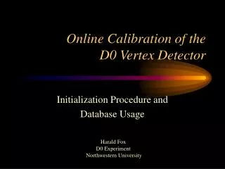
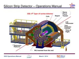
Silicon Strip Detector – Operations Manual. Heavy Flavor Tracker. SSD: 4 th layer of vertex detector. Time of Flight. PXL Inserted from this end. The Main Control Panel for the SSD. The SSD control panel should be running but if not login to ssd@ssd-upgrade.starp.bnl.gov

E N D
Silicon Strip Detector – Operations Manual Heavy Flavor Tracker SSD: 4th layer of vertex detector Time of Flight PXL Inserted from this end
The Main Control Panel for the SSD • The SSD control panel should be running but if not • login to ssd@ssd-upgrade.starp.bnl.gov • enter “shssdTop” • For normal operations push “Turn SSD On” or “Turn SSD Off” • The large circle will change from Red to Green when the detector is ready for data taking. • Yellow indicates that the detector is still in transition. • Call an expert if you have questions
Air Flow Monitor • The temperature of the cooling air is not very sensitive to the temperature of the detector. The value shown here will rarely rise above room temperature. See the “Ladder Monitor” page for more useful temperature readings. • The air flow gauge monitors the cooling air flowing through the SSD ladders • Normal reading ~ 3.5 • The interlock system will shutdown the SSD if the air cooling fails. • No operator action is required to shutdown the system although many alarms will be activated. • Recovery after a cooling failure requires an expert.
Ladder Monitor • Ladder temperature • (in 4 places) shown in the first 4 columns • FPGA status • shown by the red/green circle • Expert Info for the ladders • RDO # • the SSD has 5 RDO’s (0-4) • LC # • each RDO talks with 8 ladder cards (0-7) • Hybrid Power • Status of the hybrids (16 total) on each LC red = off, yellow = on
Power Expert • The main power should never be switched off. Fans always at 2400 RPM. • Not even in an emergency. (SSD Interlocks will automatically switch off the power in case of emergency.) • Experts only! • Use the “All On / All Off” to turn power on manually. On: 5V first, then 2V, then Bias. Off: Reverse order
Power Expert: “All On” and “Batch Mode” • Experts only! • Note Crate_1 or Crate_2 controls • Batch mode • For controlling groups of modules • All On / All Off • On: 5V first, then 2V, then Bias. Off: Reverse order • Clear Events (on HV trip) • Press Clr Events if an HV channel has tripped off. Reset HV channel manually to prescribed voltage.
Power Expert: Setting individual channels • Experts Only! • Note: complex mapping from channel # to SSD Ladder # • Highlight value to be changed, enter change and hit (CR) • (very important to hit (CR)) • Changes made here are permanent • For setting individual channels • On/Off • Set Voltage (target voltage) • Current limit • Rise rate (volts per second) • Supervision behavior (on trip) • “Sense” voltage is the actual voltage on the detector
Ladder Expert Panel for configuring ladder cards An expert can power up the SSD by selecting “All” and “All” in the RDO and Fiber menu boxes then push the buttons on the right, one by one, starting from the top RDOs and Fibers can also be configured one at a time. (In this context, “fiber” is a synonym for “ladder card”) Send Trigger is only for testing Pulser mode is only for testing
~ 50 cm Schematic Representation of the HFT SSD IST Beampipe • The STAR Heavy Flavor Tracker – the full suite • TPC – SSD – IST – PXL • TPC pointing resolution at the SSD is ~ 1 mm • SSD pointing at the IST is ~ 400 mm = 0.98 • IST pointing at PXL 2 is ~ 400 mm = 0.98 • PXL 2 pointing at PXL1 is ~ 125 mm = 0.93 • PXL1 pointing at the VTX is < 40 mm = 0.94 • = track matching efficiency Pixel Detector Note: Detector Cartoon Not a precise rendering of any of the detectors
Backup Slides Backup Slides
The SSD before inserting into the TPC Special thanks to Thorsten and Luis for this small miracle Ladder card performance is excellent Performance of ladders is about as good as in 2008 (i.e. 90-95% live modules)
SSD Location in STAR IFC Inner Field Cage OFC Outer Field Cage Magnet End Cap TPC Volume SSD Surrounds the PXL & IST @ 22 cm radius Solenoid
SSD Overview – the SSD sits on the OSC Transition Cone (w/shroud removed) WSC Outer Support Cylinder (OSC) 44 cm 20 Ladders 4.2 Meters East Support Cylinder (ESC) ~ 1 Meter
~ 50 cm SSD Parameters Note: Detector Cartoon Not a precise rendering of the detector Note: Detector Cartoon Not a precise rendering of the SSD detector • Double sided Si wafers 300 mm thick with 95 mm strips that are 4.2 cm long • Strips crossed at 35 mrad effective resolution 30 mm x 900 mm • Located at 22 cm radius • 20 ladders, 67 cm long • air cooled • < 1.2 • 1 % radiation length @ = 0
The SSD was an existing detector upgrade Existing Detector w/ Si modules Electronics Upgrade kHz rates Mechanical & Conv. systems upgraded
Ladders and Ladder Cards Foam and Mylar wrap applied to Ladders and Ladder Cards Ladders installed and tested Analog performance is excellent (analog noise < noise from modules) JTAG communications work, T readback OK Power consumption is as expected for +5V, +2 V but -2V is a bit high … may be an issue with power supplies over long lines.
Ladder Cards • The Ladder Card contains the ADC to read-out each of the Si modules • On-board FPGA • Faster, lower noise • 1 kHz (16% DT) • 10x lower noise
Survey Ladders were surveyed to ~10 m precision Typically, the wafers are positioned < 50 m wrt the goal, comparable to our resolution A small number of wafers are displaced ~1 mm The displacement due to gravity of each ladder has been measured