Introduction to MODFLOW-2005: Concepts, Techniques & Methodologies
Learn about MODFLOW-2005, the USGS ground-water model, detailed documentation, processes, and enhanced features. Suitable for existing MODFLOW users wanting to upgrade.

Introduction to MODFLOW-2005: Concepts, Techniques & Methodologies
E N D
Presentation Transcript
Versions of MODFLOW This class will use the documentation for MODFLOW-2005 as a primary reference. Class projects will be done with this version. The report and program can be downloaded to your computer from USGS web site MODFLOW MODFLOW-88 MODFLOW-96 MODFLOW-2000 MODFLOW-2005 http://water.usgs.gov/nrp/gwsoftware/modflow2005/modflow2005.html
MODFLOW-2005 Documentation Techniques and Methods 6-A16: “MODFLOW-2005, the U.S. Geological Survey modular ground-water model – the Ground-Water Flow Process” by Arlen Harbaugh • Concepts, • Input instructions, and • Programmer guide for the core packages • Replaces TWRI 6-A1, MODFLOW-96, and MODFLOW-2000 reports • There will continue to be separate reports for additional packages
MODFLOW-2005 is an updated version of MODFLOW-2000 • Structural changes to support Local Grid Refinement (LGR) • LGR will be discussed later • Structural Enhancements also facilitate interfacing with other models • E.g. GSFLOW (PRMS coupled to MODFLOW) being developed by Prudic, Niswonger, Leavesley, and Markstrom • E.g. GWM, GWT, and SEAWAT
MODFLOW-2005 is an updated version of MODFLOW-2000 • Uses parameter structure to ease the modification of data input values. • Provides expanded data input capabilities. • Program is designed to minimize changes that would impact existing MODFLOW users.
Design objectives and how they were met • Portable – run on “all” computers with minimal modification • Strict adherence to FORTRAN standards • Easy to understand • Modular program structure • Modular data input • Modules transfer data via subroutine arguments rather than through COMMON • Documentation is modular • Concepts are separated from the programming, but linked
Design objectives and how they were met • Easy to enhance • Either by modifying the model program • Modular structure • Method of equation formulation using conductance, RHS, and HCOF • Or by using with other programs (Pre and post processors) • Flexible I/O • Efficient • FORTRAN • Solvers use one-dimensional arrays
Parameter Estimation • Parameter Estimation is removed from MODFLOW-2005 • Separate programs will provide Parameter Estimation • A new version of UCODE is on the web • Observations are included in MODFLOW-2005 • Sensitivity is removed for now • UCODE provides the capability to compute sensitivities using perturbation • Sensitivity will be added again to MODFLOW-2005 in the future
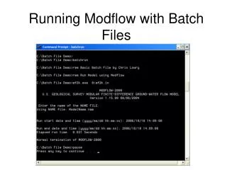
Should MODFLOW-2000 Users Switch to MODFLOW-2005? • No need to switch until you need some new functionality – for example: • LGR • New parameter estimation functionality • PRMS-MODFLOW • Same input files will work • GLOBAL file is no longer allowed • All output goes to LIST file • Programs such as UCODE and GWM will include a file that serves the purpose of the former MODFLOW-2000 GLOBAL file • The “modflow.bf” batch file capability is no longer supported • “.BAT” files can be used to obtain this functionality.
MODFLOW 2005 PROCESSES Previous MODFLOW tasks (prior to MF2K) are now defined as the: Global Process • GLO – Controls Overall Program Operation Equation Solving Processes • GWF – Ground-water Flow Process
MODFLOW 2005 PROCESSES As Initially released, MODFLOW also includes other processes: • OBS - Observation Process • SEN - Sensitivity Process • PES - Parameter Estimation Process • GWT - Ground-water Transport Process Other Processes being developed including: • FMP – Farm Process We are going to concentrate on the GWF – Ground-water Flow Process and discuss the others later in the class
GLOBAL PROCESS • Controls overall program flow • Activates capabilities (Packages) • Opens package data files (Input and Output) • Reads data for space and time discretization (DIS file) • Reads parameter files (Multplier and Zone) • Has a global level listing file The Global Process does not solve an equation
GROUNDWATER FLOW PROCESS(abbreviated list) GWF Process Packages – User Prospective • BAS6 Basic Package Hydrologic Packages • BCF6 Block Centered Flow Package • LPF Layer Property Flow Package • RCH Recharge Package • RIV River Package • WEL Well Package • DRN Drain Package • GHB General Head Boundary Package • EVT Evapotranspiration Package • STR Stream/Aquifer Package • HFB6 Horizontal Flow Barrier Package • CHD Constant-Head Package Solution Packages • SOR Slice-Successive Over-relaxation • SIP Strongly Implicit Procedure • PCG Preconditioned Conjugate Gradient
MODFLOW-2005 will evolve • Initial ground-water flow capabilities • BCF, LPF, HUF,HFB,CHD,RIV, WEL, DRN, GHB, RCH, EVT, STR, MNW, FHB, IBS,SIP, PCG, GMG, DE4 • Recently added capabilities • ETS, DRT, RES, SUB, LAK, SFR, GAG, UZF • New options in LPF • CONSTANTCV (keeps CV constant) • NOCVCORRECTION (does not apply vertical flow correction) • STORAGECOEFFFICIENT (does not multiply SS by thickness) • THICKSTART (computes thickness based on initial head)
GROUNDWATER FLOW PROCESS GWF Process Procedures – Programmer Prospective • DF Define • AL Allocate • RP Read and Prepare • ST Stress • AD Advance • FM Formulate • AP Solve Equations • OC Output Control • BD Calculate Water Budget • OT Output
GROUNDWATER FLOW PROCESSPrimary Modules Example RIV6FM • The first three characters designate the package (river) • The fourth character is the version number (6) • The last two characters represent the procedure (formulate)
MODFLOW – user perspective • Input Data • ASCII text files • Output Data • ASCII text files • Binary files • Graphical user interface (GUI) • Code Execution
MODFLOW – user perspective • BASIC INPUT ITEMS: • Grid • Time stepping • Solution parameters • Hydraulic parameters (includes material properties) • Boundary Conditions • Stresses (source-sinks) • Output options • BASIC OUTPUT ITEMS: • Hydraulic Heads • Drawdown • Flow rates • Mass Balance • Optional info at specified times • Iteration information • Binary files containing heads, drawdowns and flow rates in compressed form
GUI • Allows you to develop a nice image of model features on the computer screen and manipulate the model inputs graphically • Creates the text files and executes MODFLOW. • You never need to see the text files or know the commands that are necessary to run MODFLOW ... until something goes wrong!
GUI • Pros and Cons • Inevitably something does not work correctly • Need to have the ability to look at and understand the content of the model files and control the commands. • Likely to dislike the tedium associated with the portion of the course where we work with text files
File formats • Original code MODFLOW88 expects to have FORMATTED DATA SETS • exact about placement of data in columns of the file • Occasionally see files in an old format (may have no spaces) • MODFLOW96 provides the option of using either FREE or FORMATTED DATA SETS • Translator was released with MODFLOW-2000 • Takes MODFLOW88 or MODFLOW96 files and convert them to MODFLOW-2000/2005 • HUF package – allows geometry of the geology defined separately from the layers and have code simplify it to individual values for each model cell
File formats • Prior to MODFLOW-2000, MODFLOW required a different number in each model cell, now have flexibility in populating the cells with parameter values • Parameters • MODFLOW calculates value for each cell based on • Parameter file (PVAL) – defines values used to replace parameters specified in the files where parameters are defined (can use SEN in 2000) • Multiplier files (MULT) - specify multiplier arrays which can be used to calculate layer variables • Zone files (ZONE) – specify the cells in a layer (arrays) that are associated with a parameter
Next: LEARNING MODFLOW • Global Process • Overview of Common Packages • Basic • Utility Module • Output Control • BCF • WEL • RIV • RCH • EVT • STR • DRN • GHB • LPF • Once use to input for several packages, others are the same • Best way to learn is to build a model • In class, we will build a model for a simple problem • Work on class project
GLOBAL PROCESS DATA Name File: Contains the names of most input and output files and controls the parts of the model program that are active. Discretization File: Contains data that defines the physical size of the finite difference grid and the fundamental components of time discretization. Multiplier File: Contains data to define multiplier arrays. Zone File: Contains data to define zone arrays.
NAME FILEContains the names of most input and output files and controls the parts of the model program that are active. Example Name File twri.nam • For each simulation, in free format Ftype Nunit Fname • Ftype—is the file type with special character values. It is not case specific. • Nunit—is the Fortran unit to be used when reading from or writing to a file. • Fname—is the name of the file. Pathnames maybe specified. Name File is read on unit 99. Comments are indicated by the # character in column 1.
FTYPE Basically “key words” that are fixed: List for the forward run listing—if this file is not present, the Global file is used for the forward run listing as well as for the global listing The GLOBAL FILE was only supported in MODFLOW-2000. In MODFLOW-2005, all of the listing is in the LIST file. It must be the first non-comment record.
Global Process Files DIS Discretization MULT Multiplier Array ZONE Zone Array GWF Process Packages BAS6 Basic OC Output Control BCF6 Block-Centered Flow LPF Layer Property Flow HFB6 Horizontal Flow Barrier RCH Recharge RIV River WEL Well DRN Drain GHB General-Head Boundary EVT Evapotranspiration STR Stream-Aquifer CHD Constant-Head GWF Solvers Packages SIP Strongly Implicit Procedure SOR Slice-Successive Over- Relaxation PCG Preconditioned Conjugate Gradient DE4 Direct Solution FTYPE CONTINUED
FTYPE CONTINUED Data Files DATA(BINARY) A binary (unformatted) file such as those used to save cell-by-cell budget data. Rewound for parameter estimation DATA A formatted (text) file such as those used to save heads and drawdown, and for input of data from files that are separate from primary package input files. Rewound for parameter estimation. Data Files For Parameter estimation (we probably won’t use these) DATAGLO(BINARY) A binary file (unformatted)—Not rewound DATAGLO A formatted (text) file—Not rewound
DISCRETIZATION FILEContains data that defines the physical size of the finite difference grid and the fundamental components of time discretization. • All discretization data in one place • Elevations always included even if GWF does not need because there is a good chance other processes will need it • Not always included originally in order to save memory
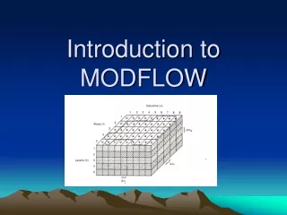
DISCRETIZATION FILEContains data that defines the physical size of the finite difference grid and the fundamental components of time discretization. Horizontal Discretization • Columns are numbered starting from the left side of the grid • Rows are numbered starting from upper edge of grid • Horizontal grid dimensions are specified in variables DELR and DELC. • All cells in a column have the same width so there is one value of DELR for each of the columns. • There is one value of DELC for each of the rows
DISCRETIZATION FILE CONTINUED Vertical Discretization • Layers are numbered from the top layer down. • Elevation of the top of layer 1 is defined in addition to the bottom elevation of every layer. • Cell thickness is calculated from the elevation information. • Below each layer, except for the bottom layer, there may be a confining unit where only vertical flow is treated (Quazi 3d). • For the confining units, the elevation of the bottom of bed is defined. For each layer, the present or absents of a quazi-3D confining bed must be indicated (LAYCBD).
DISCRETIZATION FILE CONTINUED Time Discretization The fundamental component of time is the time step. Time steps are grouped into stress periods. Time dependent input data can be changed every stress period. Specified by user each stress period: PERLENLength of stress period TSMULT Time step multiplier NSTP Number of time steps in a stress period If TSMULT>1, the length of the first time step (Δt1) is determined from the following equation for a geometric series: And for 2≤m≤NSTP,
DISCRETIZATION FILE CONTINUED • MODFLOW can simulate steady state (SS) or transient conditions (TR). • A single stress period length is specified for steady state and only a single time step is required. • Individual stress periods in a single simulation maybe either steady state or transient. • The steady state and transient stress periods can occur in any order.
DISCRETIZATION FILE CONTINUED • Within the listing outputs, units of length and time may be labeled • ITMUNI indicates the time label: 0 – undefined 3 – hours 1 – seconds 4 – days 2 - minutes 5 – years • LENUNI indicates the length label: 0 – undefined 2 - meters 1 - feet 3 – centimeters Note: Be sure to use consistent units for all input data!
DISCRETIZATION FILE CONTINUED Discretion File Data Spatial • NROW Number of rows • NCOL Numberof columns • NPER Number of stress periods • ITMUNI Time unit • LENUNI Length unit • LAYCBD Quazi 3D confining layer indicator. There is one value for each layer. LAYCON =1→Confining unit LAYCON=0→No confining unit • DELR Cell width along the row, there is one value for each NCOL columns. This data is read using a utility package (U1DREL) Discretion File Data Example
DISCRETIZATION FILE CONTINUED • DELC Cell width along the columns, there is one value for each NROW rows. This data is read using a utility package (U1DREL) • Top Top elevation for Layer 1. This data is read using a utility package (U2DREL) • BOTM The bottom elevation. There is one for each layer and quazi 3D confining layer. This data is read using a utility package (U2DREL) Discretion File Data Discretion File Data Example
DISCRETIZATION FILE CONTINUED Discretion File Data Temporal • PERLEN The length of a stress period • NSTP Number of time steps in a stress period • TSMULT Multiplier for the length of successive time steps • Ss/Tr Is a character variable that indicates if a stress period is transient or steady state, TR Transient SS Steady State Note: The four temporal variables are read for each stress period. Discretion File Data Example
Data to Define Terms for the Flow Equation • Arrays – one value for every cell in one or more layers • Example: Hydraulic Conductivity, Initial Head • Lists – one or more values at cells that are identifed by layer, row, and column • Example: Wells, Streams • Methods of defining data • Values directly read from files • Values constructed from parameters
PARAMETERS • Generic meaning of “PARAMETER” • Any input data for a model • Meaning of “PARAMETER” IN MODFLOW-2005 • A specially designed value that can define input values for many cells • Changing the parameter value changes all of the associated input values • Parameters are used in the Parameter-Estimation Process because there is not enough data to estimate all types of inputs for all cells. • Parameters are a convenient way to specify input data even if not using the Parameter-Estimation process.
PARAMETER DEFINITION • Parameters can only be specified for part of the input data: • LPF, CHD, GHB, RIV, DRN, WEL, RCH, EVT, HFB allow parameters • Array parameters • For each layer, specify multiplier and zone arrays • NONE is a special multiplier array • ALL is a special zone array • If an array is defined using parameters, values for all cells in all layers must be defined by the parameters – i.e. cannot define values for some cells using parameters and some without using parameters • Additive parameters • List parameters • Can mix parameters with non-parameter data • Additive parameters
PARAMETERS Layer or Array Data • A value is required for every cell in one or more horizontal of the grid (e.g. hydraulic conductivity) • Data can either be read using the utility modules or using parameters, but the same method must be used consistently for any data type (e.g. if parameters are used to define hydraulic conductivity in a layer, then parameters must be used to define hydraulic conductivity for all the layers).
PARAMETERS ListData • One or more values at cells that are identified by layer, row, and column (examples – wells, stream cells) • Data values are required for only some of the cells (e.g. cell that have river nodes). • MODFLOW-2005 allows only some list data to be defined using parameters (e.g. streambed conductance, but not stage or river bottom elevation). • Parameters can be used, or one line of data can be read for each cell for which the data is required. • It is generally possible to define some values in the list by directly reading and other values in the same list through parameters.
PARAMETERS When parameters are used for list data, the data value for the cell is calculated as the product of the parameter value, which may apply to many cells, and a cell multiplier or factor, which applies only to the cell.
PARAMETERS • When parameters are used for array data, multipliers are defined using multiplier arrays. • There may be a different multiplier array for each layer and each parameter type . • If a specific parameter type has more than one parameter values for a layer, azone array is used to assign specific values to specific cells. • There can be a differentzonearray for each layer and each parameter type.
PARAMETERS • The data value in a cell can be determined by more than one parameter. • If two or more parameters of the same type include the same cell, the final data value equals the sum of the contributions for all of the parameters. • When two or more parameters are used to define the value for cells, the parameters are said to be additive.
PARAMETERS Multiplier Array for P1 Example: Use of two parameters to determine layer datavalues for the same cells. • It is desired to have a hydraulic conductivity distribution (layer data) vary linearly from 10 to 100 from the left side to the right side. • Let P1 and P2 be the two parameters with multiplier arrays shown on the right. Multiplier Array for P2
PARAMETERS P1=10 and P2=100 • The contributions from both parameters will be added as indicated in the upper right table. • The final result is shown in the lower right table. Note: The same distribution could have been created otherways. Final Result
PARAMETERS Parameter P1 Data List Example: Use of two parameters to determine list data values for the same cells. • Streambed conductance is assumed to be a mixture of two types of material: coarse grained (P1) and fine grained (P2) • Parameters P1 and P2 both include the five cells where the two river bed materials are intermixed. Parameter P2 Data List
MULTIPLIER FILE TEXT The # character in column 1 and any type of characters there after up to 199 in number. Used for comments. NML The number of multiplier arrays to be defined. MLTNAM Name of multiplier array. May be up to 10 characters in length and is not case sensitive. FUNCTION Optional keyword indicating that a multiplier array will be constructed from other multiplier arrays.