Higgs Factory Backgrounds
570 likes | 599 Vues
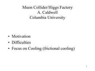
This workshop presentation provides an introduction to the background spectrum and fluxes at the central part of the detector in Fermilab's Higgs Factory. It discusses the basic characteristics of the backgrounds coming into the detector and analyzes hits in the vertex detector. The presentation concludes with a comparison of different versions of the HF MDI and the locations where background particles enter the detector.

Higgs Factory Backgrounds
E N D
Presentation Transcript
Fermilab Accelerator Physics Center Higgs Factory Backgrounds Sergei Striganov Nikolai Mokhov and Igor Tropin Fermilab MAP 2014 Spring Workshop Fermilab 27-31 May, 2014
Outline • Introduction • Background spectrum and fluxes at central part of detector • Basic characteristics of backgrounds coming into detector • Hits in vertex detector • Conclusion
HF MDI Versions – MAP12 • No nozzles, no other MDI shielding • v0 - minimal 7.6 deg, 5σ nozzles • v1 - minimal 7.6 deg, 5σ tungsten nozzles, tungsten collimator in IR and concrete collars in IR • v2 - thicker 15 deg, 4σ tungsten nozzles in BCH2 cladding, 5 sigma tungsten collimator in IR, concrete colars in IR, new magnets geometry, magnetic field maps • v3 – additional shielding installed around first quad. • Tungsten collimators reduced to 4 sigma. Beam pipe • radius near IP enlarged from 3 to 5 cm. Minor • changes in inner nozzle surface.
Where is Background Enters Detector?V2 – MAP13 70% gamma, 80% e+-, 60% of hadrons coming into detector through quad (Z>350cm and R > 50 cm) – more than 15 ns from IP.
Gamma Flux (1/cm2/bunch X) without nozzle v3
Gamma Flux in Plane Perpendicular to Beam at IP (1/cm2/bunch X) without nozzle v3
Electron/Positron Flux (1/cm2/bunch X) v3 without nozzle
Electron/Positron Flux in Plane Perpendicular to Beam at IP (1/cm2/bunch X) v3 without nozzle
Neutron Flux (1/cm2/bunch X) without nozzle v3
Neutron Flux in Plane Perpendicular to Beam at IP (1/cm2/bunch X) without nozzle v3
Where Background Hits Nozzle INNER surface-v3 2.2 105 decay e+- through Be beam pipe (25 GeV/c)
Angle between electron/positron and beam as function of nozzle entrance point
Momentum spectra of electron from muon decay and momentum spectra of electron entered into nozzle (|z|<120 cm)
Where Background Hits Nozzle INNER surface -II v3 nozzle Reduced v3 nozzle
Where Background Hits Nozzle INNER surface -III v3 nozzle: 2.2 105 decay e+- through Be beam pipe (25 GeV/c) reduced v3 nozzle: 106 decay e+- through Be beam pipe (25 GeV/c)
How to choose minimal nozzle radius? electron distribution after first quad 350 cm from IP minimal nozzle radius
Where Background Hits Nozzle INNER surface -IV v4 nozzle- no decay electron through Be beam pipe v7 – no decay electron through Be beam pipe
Electron flux near IP for different nozzle inner shapein accelerator plane v3 nozzle: electron/cm2/BX v7 nozzle: electron/cm2/BX
Electron flux at IP in Plane Perpendicular to Beam v3 nozzle: electron/cm2/BX v7 nozzle: electron/cm2/BX
Gamma flux near IP for different nozzle inner shapein accelerator plane v3 nozzle: gamma/cm2/BX v7 nozzle: gamma/cm2/BX
Gamma flux at IP in Plane Perpendicular to Beam v3 nozzle: gamma/cm2/BX v7 nozzle: gamma/cm2/BX
Neutron flux near IP for different nozzle inner shapein accelerator plane v3 nozzle: neutron/cm2/BX v7 nozzle: neutron/cm2/BX
Neutron flux at IP in Plane Perpendicular to Beam v3 nozzle: neutron/cm2/BX v7 nozzle: neutron/cm2/BX
Gamma Flux in Plane Perpendicular to Beam at IP (1/cm2/bunch X)
e+- Flux in Plane Perpendicular to Beam at IP (1/cm2/bunch X)
Neutron Flux in Plane Perpendicular to Beam at IP (1/cm2/bunch X)
Background File Simulation • Simulation of background particles coming into detector takes a lot of CPU. • To look at detector background in detail file with particles on some interface surface is prepared. Different detector geometries and different codes (Geant4, Fluka) can be used in further studies starting from this file. • Muon decay points are simulated randomly from -23 to 23 m from IP using MARS code. Electron/positron shower in accelerator structure is simulated. Calculation is stopped at interface surface. Following results were obtained with cutoff energies (±23 m from IP): • neutron - 100 keV, muon– 1 MeV, • charged hadron - 1 MeV, • gamma, e± - 200 keV.
Where is Background Produced?Number of Particles Entering Detector
Momentum Spectra of Particles Entering Detector: v3 and v7 v7: 92% of e+- momentum < 0.5 MeV/c
Where background enters to nozzle - v7? Most of electrons/positrons are produced from nozzle jaws
Gamma flux: entrance to detector vs entrance to nozzle.Beam pipe – 5 cm radius, nozzle minimal radius – 2 cm vertical coordinate horizontal coordinate Maximum at positive (negative) entrance to nozzle and negative (positive) entrance to detector – backscattering from nozzle jaws!
Number of particles entering detector per bunch X-ing.ch. Hadron > 1 MeV; γ,e > 0.2 MeV; neutron> 0.1 MeV
Hit calculations • MARS improvements : all weights equal 1 and EGS5 simulation up to 1 keV. We can simulate hits now! • Hit definition: charged track left sensitive volume + charged • track is stopped in sensitive volume. To estimate occupancy we • need to perform simulation for chosen pixel size. Appropriate • electron transport threshold should be determined as function of • pixel size. • In MARS minimal energy of produced δ-electron Ed= electron • transport threshold. Number of produced δ-electron ~ 1/Ed . Low energy • δ-electron are produced with large angle to δ-electron direction. • Electron ranges in silicon:3 keV – 0.14 μm and 10 keV – 1.5 μm. • With 3 keV threshold most of δ-electrons are stopping in same pixel as • outgoing track - double counting! 10 keV threshold looks like more • realistic.
ILC experience – Tatsuya Mori (Tohoku University) Important numbers: pixel size 5-10 μm and occupancy < 3%