Deformation (& deformation modes)
320 likes | 397 Vues
Learn about deformation, stress, structures, materials, mechanical properties, and failure in materials science and engineering. Understand forces, moments, loads, and testing components. Discover strategies for avoiding material failure.

Deformation (& deformation modes)
E N D
Presentation Transcript
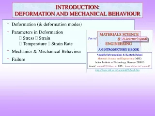
Deformation (& deformation modes) Parameters in Deformation Stress Strain Temperature Strain Rate Mechanics & Mechanical Behaviour Failure MATERIALS SCIENCE & ENGINEERING Part of A Learner’s Guide AN INTRODUCTORY E-BOOK Anandh Subramaniam & Kantesh Balani Materials Science and Engineering (MSE) Indian Institute of Technology, Kanpur- 208016 Email:anandh@iitk.ac.in, URL:home.iitk.ac.in/~anandh http://home.iitk.ac.in/~anandh/E-book.htm INTRODUCTION:DEFORMATION AND MECHANICAL BEHAVIOUR
Materials, Structures and Mechanisms • Broadly we can think of materials, structures and mechanisms. • Structures and Mechanisms are made of materials. • A structure (like a building or an anglepoise lamp) may perform multiple roles, but typically all of them bear load. • A mechanism is typically used to transfer power and may involve change in direction, speed or torque. • Compliant mechanisms are structures which play the role of a mechanism. • Structures typically have positive stiffness (i.e. resist the load), but may develop negative stiffness under special circumstances (e.g. buckling)
Let us start with some basic definitions and considerations • We can apply forces and moments on a body. • Force(s) can be applied on a body in two ways: (i) Surface forces (by direct contact of one body with another) & (ii) Body forces (force exerted without direct contact, usually throughout the volume of the body). Hammering involves surface forces, while gravitational pull is a body force. • The force can be: (i) Point force (if the area of application is small compared to the overall area of the body) or (ii) Distributed load (loading is over an area). • The force or moment experienced by a member may arise from a ‘support’. A support which prevents translation in a direction gives rise to force in that direction. If on the other hand rotation is prevented, then this results in a moment.
Some simple structures • In simple structures like buildings, the load is transmitted to the foundation via beams and columns. • A beam carries loads which act at right angles to the length of the beam, which spans horizontally between supports. They have a small cross-section in comparison to their span. In general the external loads on a beam results in bending moments (M) and shear forces (V). • Some types of beams are: (i) Simple supported (ii) Fixed (iii) Cantilever (iv) Continuous (vi) Overhanging(vii) Restrained.
Behaviour of Components in Service and the Testing of Materials • Components and devices in service have to satisfy certain ‘performance parameters’ (load to borne, temperature of operation, environment of operation, etc.). • To satisfactorily perform under a given service conditions, the material should possess certain properties. And, we would like to avoid failure# of these components/devices. • Before we design and test components, we would like to know about the material properties (on which we can base our design). Also, often it is difficult to test entire components (like a gear wheel) or a system of components (like a gear wheel assembly). • Usually, special ‘test rigs’ are designed to test a ‘full’ components or an assembly of components. • Hence, often we rely on test data on ‘model’ samples, with ‘ideal’ geometries. These tests include: hardness test, uniaxial tension test, bending test (3-point, 4-point), torsion test, hardness test, creep test, etc. • The challenge is to use this data obtained from model tests, for the design of components. The component may have a complicated geometry and which experiences a state of stress, which is considerably different from that in the model test. • In the design of structures the (i) strength (), (ii) deformation () and (iii) stability are taken into account. # Failure implies deviation from desired performance.
In general failure can be avoided by: (i) a better design of the system (such that the component experiences a lower ‘degree of loading’) and/or (ii) better design of the component. Further, the improvement in the component design could involve a better: (i) geometrical design and/or (ii) material design (i.e. choice of material). • Another way of looking at ways to avoid material failure is: Protect the material (paint to avoid corrosion, cool the material if ‘heating’ is leading to failure) Make a ‘better’ material (design a material to withstand high temperatures, if creep is leading to failure) Have a ‘sacrificial strategy’ (have a sacrificial anode which will corrode in preference to the material of interest, have a shield which will burn up during re-entry of a space vehicle thus protecting the interior) • Most of the engineering failures (~70%) happen due to fatigue and corrosion. • In this chapter we will concern ourselves only with mechanical properties.
What kind of mechanical behaviour phenomena does one have to understand? • Phenomenologically mechanical behaviour can be understood as in the flow diagram below (1) Elasticity, (2) Plasticity, (3) Fracture, (4) Fatigue, (5) Creep. • Multiple mechanisms may be associated with these phenomena (e.g. creep can occur by diffusion, grain boundary sliding etc.). • These phenomena may lead to the failure of a material#. • Many of these phenomena may occur concurrently in a material. Mechanical Behaviour Release Pushing a spring Regains Original length Original length Elasticity Recoverable deformation Plasticity Permanent deformation Bending of rod of metal A phenomenological classification (not a mechanistic one) Fracture Propagation of cracks in a material* Crack Propagation Crack Propagation Fatigue Oscillatory loading Creep Elongation at constant load (/constant stress) at ‘high’ temperatures # Failure implies deviation from desired performance. * Eventually can lead to breaking of material.
There seems to be many ‘phenomenological’ possibilities of deformation (elasticity, plasticity, creep, ...). In a given situation which one will be operative? Funda Check • Each of the phenomenological effects (let us consider creep) may have multiple mechanisms which may give rise to the effect (in creep, grain boundary sliding and diffusion are two of the possible mechanisms). The ‘effect’ in the current context could be an observable like ‘irreversible deformation’ (i.e. plastic deformation). • When there are two (or more) competing mechanisms are available to respond to a stimulus (say applied load which results in a stress state in the material), then the mechanism which operates at a lower magnitude of the stimulus (stress in the current situation) operates (in preference to other competing mechanisms). • Material variables (like grain size, segregation, crystal structure, etc.) and process variable/loading conditions (like temperature, strain rate) will play a key role in determining the mechanism which will be operative.
Notes on the Classification of Mechanical Behaviour • The classification presented is for ‘convenience’ and many details have been ignored. • In the uniaxial tension test (loading of specimen in uniaxial tension), dislocation ‘activity’ starts well below the yield stress (as we shall see later)→ plasticity in the microscale (in the ‘elastic’ region!!). • Creep also leads to ‘plastic deformation’! • Fracture in ductile material also involves plasticity at the crack tip level. • During fatigue loading (loading oscillating in load/stress, usually below the yield stress), dislocation activity can lead to surface intrusions and extrusions (plastic deformation at the microscopic level). • Plastic deformation is volume conserving, while elastic deformation (in general) is not. • Hydrostatic states of stress tend to cause volume changes, while shear stress tend to cause shape changes. • On the application of load/constraint to a material, in may respond in many ways. The response could be reversible (elastic deformation) and or irreversible (plastic deformation & fracture). • The response to the load could be ‘immediate’* or could occur over a period of time. • In some cases (creep and fatigue) the damage may accumulate over a period of time before the component/sample ‘fails’. * More will be said about that, when we talk about anelasticity and creep.
What kind of mechanisms can lead to ‘failure’? If failure is considered as deterioration in desired performance*- which could involve changes in properties and/or shape; then failure can occur by many mechanisms as below. Mechanisms / Methods by which a Material can FAIL Elastic deformation** Bond distortion Chemical /Electro-chemicaldegradation Creep Physicaldegradation Fatigue Plastic deformation Fracture Cracks Microstructuralchanges Twinning Wear Slip Dislocations Twinning Erosion Corrosion Etc. Phase transformations Oxidation Grain growth * Beyond a certain limit Particle coarsening ...and more. ** Some may wonder as to how elastic deformation can be construed as failure.
Funda Check How can elastic deformation lead to (/constitute) failure? • From a ‘common sense’ perspective, fracture seems to be the ‘real’ failure. • With a little ‘stretch’ we can think of plastic deformation as also ‘failure’. • But, how can elastic deformation constitute ‘failure’? • Let us consider a diving spring board (in a swimming pool). • To get a good dive one needs a good jump. For this the board should provide a good ‘spring-back’. • If the compliance of the board is too much the board will bend and the swimmer will just fall into the pool. The board after some oscillations will return to the approximately horizontal position (i.e. the process is elastic but the board has failed to deliever the desired performance). • However, in most circumstances permanent change in the shape of the component (i.e. involving plastic deformation) or fracture is considered as failure. • Such a failure by plastic deformation and/or fracture can occur due to phenomenological processes like creep and fatigue. • In ductile materials, plastic deformation usually precedes fracture. If acceptable deflection is exceeded Material is elastic but > c In general If Yield stress is exceeded Failure Plastic deformation is initiated ( > y) If fracture stress is exceeded The material fractures ( > f)
Common types of loading and deformation • From a macroscopic perspective we can deform a material in by applying (i) external forces (or (ii) moments) in a few ways. The actual loading on a given component may be complex, involving combinations of these loading types. Tension/CompressionBendingShear Torsion. • The kind of loading employed is often dependent on the geometry of the sample (e.g. bending is done on thin long samples, while compression on short cylinders). • The deformation mode experienced by the material and the mechanism(s) involved at the microscopic level has to be separately analyzed. E.g., in a spring, even if tension is applied, a cross-section experiences torsion. Bending Deformed configuration Torsion Note: modes of deformation in other contexts will be defined in the topic on plasticity Shear Tension Compression
In a given scenario the general loading will be a combination of the types of loading considered previously. • Basically, we can apply* either:(i) Forces (axial or shear) or(ii) Moments (bending or twisting) Transverse force * As must be obvious to the reader, often one kind of loading employed may result in other kinds of effects at the level of the body/material. E.g. a transverse force can result in shear forces and bending movements.
Deformation: a fundamental perspective At a more fundamental (material) level there are only two types of deformations$,%: • Tension/compression wherein bond length is increased/decreased Usual tension/compression During bending • Shear bond angle is distorted Usual shear Torsion* • In this chapter (and the course), (most of the time) we will assume that the loading is applied slowly (quasi-statically) i.e. wave propagation and contact damage effects can be ignored. $ A general case is a mixture of the two. % In the extreme case the bonds might break. * In torsion the strain varies radially outward.
Funda Check What can happen to a ‘material’ body (solid) on the application of external loads/forces/constraints? Contraction/dilation Volume change What can happen to a material body (solid) when we apply forces/constraints to the outside of the body Or a combination of these Shear Shape change Rigid body rotation Orientation change Example showing how parts of a single body may have different responses to loading The region between supports is stressed 3-point bend test Normal reactions The region outside the supports undergoes rigid body rotations and is not stressed
What distributed and point loads? What is a rigid body? What are contact and body forces? Q & A • In practice the kind of loads which is applied on materials (structures and mechanisms) is distributed (i.e. spread over an area). Point load is an idealization. Sharp, pointed loads will lead to very high pressures/stresses (infinite in the limit of geometrical point). This will further damage the surface of the material locally. • Similarly a rigid body is an idealization. A rigid body does not undergo any deformation. For a rigid body to be in equilibrium the sum of the external forces has to be zero. If there exists a net force then the body will accelerate (Fresultant = mbodya). • Forces applied on the surface are called contact forces. On the other hand forces like gravity act over all the particles in the entire body and are referred to as body forces. Q & A What is the difference between external force and internal response of a material? • Let us consider the pulling of a body (say a metal with the elastic limit). At equilibrium the internal force (P’) is equal and opposite to the external force (P). This can be better visualized using a cut in the body CC’. The internal force appears due to stretching of the bonds. Materials have positive stiffness and resist deformation. • Structures on the other hand may display negative stiffness under special circumstances (like during buckling).
Funda Check What is the difference between simple and pure shear? • Usually we apply ‘simple shear’ forces on a body. Though this is called simple shear it is clear that with just two forces the body will not be in equilibrium (moment balance is not satisfied). This implies that there has to be additional ‘hidden’ forces (as shown in Fig.1b). These forces ensure moment balance. To understand this let us consider a block on a table being sheared by force ‘T’. Friction provides the opposite force on bottom surface (T). • At the material level, pure shear can be considered as simple shear + rotation of /2 (for small shear). Fig.1 b c a Note the bottom For small deformations Usually we apply simple shear forces on a material Simple Shear The way the diagram is drawn the body is not in equilibrium! Pure shear of /2 = Simple shear of + ACW rotation of /2 Shear OR Pure Shear Simple shear of = Pure shear of /2 + CW rotation of /2
Funda Check What is the difference between three-point and Four-point bend test? • In bending we would like to apply pure bending moments. In practice we employ a 3-point or 4-point bend test. • In the 3-point bend test the bending moment is not constant and additionally shear forces are present. • A constant bending moment, along with zero shear forces are obtained between the loads in the case of the 4-point bend test.
Types of Deformation From a common perspective we can have two types of deformation. • Elastic Deformation wherein body recovers its original shape after removal of ‘force’.Elastic deformation is reversible. E.g. a compression of a spring the spring comes back to its original shape after load/force is released. • Plastic Deformation permanent deformation (body does not recover its shape after forces are removed.Plastic deformation is irreversible (involves dissipation of energy). E.g. bending an Al rod to a new shape the rod does not come back to its original shape after being bent. Elastic Deformation Plastic • Net deformation in a body can comprise of elastic and plastic parts. • Elastic deformation may be linear or non-linear. • There might also be a time dependent component to deformation (i.e. after application of force, full strain may be realized after some time). • Plastic deformation may be caused by many mechanisms (slip, twinning, phase transformation etc.) More about these later
How to cause elastic deformation? • Deformation* can be in:Force control mode [loads (e.g. hanging weights on a specimen), forces are controlled] Displacement control mode [a given displacement imposed on the specimen]. • Elastic deformation survives only for small strains in many materials (e.g. metals and ceramics). At larger strains other mechanisms of deformation may take over (e.g. plasticity, fracture, creep etc.).In elastomers like rubber large elastic strains may be obtained. • Applied load can cause other effects like phase transformation etc. which may also additional change in the size/shape of the material. • Deformation (internally represented as stresses and strains) can be caused by other agents apart from loads (e.g. heat, electric field, magnetic field in appropriate materials). • What is a spring? A spring can be thought of as a ‘device’ which changes tensile loading to torsional loading at the fundamental (material) level! • What is a conducting solenoid?A current carrying wire produces circular magnetic fields. A solenoid can be thought of as a ‘device’ to covert circular fields to a linear field (in the core of the solenoid) it some sense the opposite of the spring above.
Forces and Stresses (Here we restrict ourselves to ‘solid bodies’) • One can only apply forces or loads (we cannot apply stresses!). • In some sense we can also impose displacements. • Stresses develop inside the body (Often in response to external loads and constraints but not always! E.g. dislocations in materials lead to stress fields, even in the absence of external loads). * We can also impose constraints which can result in stresses in the body (we can heat a block between two ‘rigid’ walls and stresses will develop in the block). On Heating stresses develop in the body • Elastic deformation may be linear or non-linear. • There might also be a time dependent component to deformation (i.e. after application of force, full strain may be realized after some time. • The quantities of relevance inside the material are stress and strain and not load and displacement(i.e., what the material ‘experiences’ is stress and strain). More about this later.
Stress and Strain • When a load/force or a displacement is applied to a material stresses and strains develop within the material. (Note that we cannot apply stresses, they develop within a material in response to an applied load etc.). Loads/forces are typically applied on the exterior of the material (referred to as contact forces). Body forces are applied throughout the body (e.g. gravitational force acts on all particles in a body). • Stress (ij) and strain (ij) are second order tensor quantities, requiring 9 values to be prescribed in 3D (4 in 2D). • In normal materials stress and strain are symmetric tensors (symmetric about the diagonal) and hence it is enough to specify 6 values in 3D (3 in 2D). • At a fundamental level stress or strain can be tensile/compressive or shear. Tensile/compressive stresses lead to volume changes while shear stresses lead to shape changes. Under a general load the body will undergo both volume and shape changes. • In 1D*, for small values of strain, stress and strain can be defined as follows: = load/area [units: N/m2 or Pascal], (symbol is sometimes used for shear stresses) = change in length/original length [units: dimensionless] • Strain can be separated into elastic part (which is recoverable) and plastic part (permanent). Click here to know more about stress and strain * Note that these definitions are applicable only in 1D. The symbol is also used for the shear components.
Stress and Strain (cotd.) **Note** • It should be noted that under certain circumstances: (i) Stress can exist without ‘net’ strain (strain free stress) heating a body between rigid walls (ii)Strain can exist without stress (stress free strain) heating a free-standing body • Stress free strains are also observed during phase transformation On Heating Stress free strain Strain free stress Why strain? (i.e. strain versus displacement) • A point in a body may move a lot but may not ‘feel’ any strain (and may not be associated with strain energy), like in rigid body translation or rotation. • If a point in the body moves by u (say in the x-direction) and the neighbouring point moves by (u+u) then the body has been strained (as the bonds have been stretched).
Funda Check What does one imply when he/she says: “I applied stresses” (say shear stresses)? • We had noted before that we cannot apply stresses we only apply forces/loads/constraints. • The forces are typically applied on the external surface of the body; but we can apply body forces too (body forces are applied throughout (or to a part of) the volume of the body; i.e. to every point in the body). Origins of body forces include: (i) gravity mass in a gravitational field, (ii) magnetic force magnetic object in a magnetic field, (ii) electric force charged body in a electric field. • So what does one mean when he/she says that “I applied stress”?!He/she usually implies that a force was applied on a given area of material (on the surface). If the force was normal to the surface tensile/compressive force If the force was tangential to the surface shear force. • Constrains can also lead to stresses. E.g. if we keep a metal rod between two ‘rigid’ walls and heat the metal, it will tend to expand. As the expansion is constrained, stresses develop within the body. • Stresses can also exist within a body without the application of external forces, loads or constraints*. This is referred to as residual stress. Some examples of origins of residual stresses are: thermal, dislocations and coherent precipitates. * Such a body is referred to as a free-standing body and equation (1) is valid for such a body).
How are stress and strains related to the external loading? • Even when externally a tension is applied, regions in the material may experience shear stresses this is an important aspect as microscopically plastic deformation is caused by shear stresses and one observes that plastic deformation can be caused by externally applied tension on a specimen. • To understand this let us consider a small square region ‘R’ in a specimen. • Under the action of the applied load (in the elastic region) the square region R becomes a rhombus. [Plane stress (2D stress) conditions have been assumed here]. A square can become a rhombus only by the action of shear stresses. This implies that there must be shear stresses acting on the planes ‘p1’ and ‘p2’ (figure below). • Note: even if we apply normal loads, shear stresses can develop within the material and vice-versa. Normal stresses on faces not shown Learn more about State of Stress and Strain
What is the stress and strain state arising form simple types of loading. • We consider the types of loading in the figure to the right. Tension/Compression
Parameters (Variables) in Deformation • We have already seen two important parameters (variables) in deformation → , . • Materials typically ‘soften’ on heating and hence temperature (T) is an important variable. Materials which are brittle at room temperature may also become ductile due to heating. • The rate of loading, which translates into strain rate is another variable →materials which are ductile under slow rate of loading may behave in a ‘less ductile manner’ which loading rate is faster. Typically the strain rate has to be varied by a few orders of magnitude to observe appreciable effects. • At low temperatures strain and strain hardening exponent (n) are important variables.At high temperatures strain rate and strain rate sensitivity (m) are important variables. • In terms of the effet on the plastic deformation behaviour of a material, an increase in strain rate can be visualized as a decrease in temperature. • We will come across other variables as we go along. Variables in deformation n m Strain hardening exponent Strain rate sensitivity
What kind of constitutive models (of deformation) can we consider? • A constitutive model relates stress, true strain, strain rate and temperature. • Typically, the temperature and strain or strain rate is kept constant. • Models with increasing degree of complexity are as below. Sometimes these models are to simplify the analysis. Linear elastic. (Close to the behaviour of brittle materials). Non-linear elastic. Elastic-plastic with constant flow stress. Elastic-plastic with strain hardening (linear flow behaviour) Elastic-plastic with strain hardening (non-linear flow)(Close to the behaviour of ductile metallic polycrystals, e.g. Al at RT ). More complex behaviour. A B Other terms in this context: Anelastic, Viscoelastic, Hyperelastic D C E