Chapter 5: Deformation
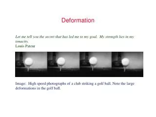
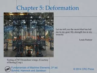
Chapter 5: Deformation. Let me tell you the secret that has led me to my goal. My strength lies in my tenacity . Louis Pasteur. Testing of 787 Dreamliner wings. (Courtesy of Boeing Corp.). Moment-Curvature Relations. In terms of ordered derivatives:.

Chapter 5: Deformation
E N D
Presentation Transcript
Chapter 5: Deformation Let me tell you the secret that has led me to my goal. My strength lies in my tenacity. Louis Pasteur Testing of 787 Dreamliner wings. (Courtesy of Boeing Corp.)
Moment-Curvature Relations In terms of ordered derivatives:
Design Procedure 5.1: Deflection by Singularity Functions • Draw a free-body diagram showing the forces acting on the system. • Use force and moment equilibria to establish reaction forces acting on the system. • Obtain an expression for the load intensity function for all the loads acting on the system while making use of Table 2.2. • Integrate the negative load intensity function to give the shear force and then integrate the negative shear force to give the moment. • Make use of Eq. (5.9) to describe the deflection at any location. • Plot the following as a function of x: • Shear • Moment • Slope • Deflection
Beams Figure 5.1: Cantilevered beam with concentrated force applied at free end. Figure 5.2: Free-body diagram of force anywhere between simply supported ends. (a) Complete beam; (b) portion of beam.
Example 5.3 Figure 5.3: Cantilevered beam with unit step distribution over part of beam. (a) Loads and deflection acting on cantilevered beam; (b) free-body diagram of forces and moments acting on entire beam; (c) free-body diagram of forces and moments acting on portion of beam.
Example 5.4 Figure 5.4: Pinned-fixed beam with concentrated force acting anywhere along beam. (a) Sketch of assembly; (b) free-body diagram of entire beam; (c) free-body diagram of part of beam.
Beam Deflection Table 5.1: Deflection for common cantilever and simply-supported beam conditions. See also Appendix D.
Example 5.5 Figure 5.5: Beam fixed at one end and free at other with moment applied to free end and concentrated force at any distance from free end. (a) Complete assembly; (b) free-body diagram showing effect of concentrated force; (c) free-body diagram showing effect of moment.
Stress Elements Figure 5.6: Element subjected to normal stress. Figure 5.7: Element subjected to shear stress.
Strain Energy Table 5.2: Strain energy for four types of loading.
Example 5.8 Figure 5.8: Cantilevered beam with concentrated force acting at a distance bfrom free end. (a) Coordinate system and significant points shown; (b) fictitious force, Q, shown along with concentrated force, P.
Example 5.9 Figure 5.9: System arrangement. (a) Entire assembly; (b) free-body diagram of forces acting at point A.
Example 5.10 Figure 5.10: Cantilevered beam with 90°bend acted upon by horizontal force, P, at free end.