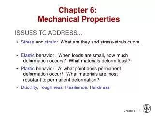
CHAPTER 3: INELASTIC DEFORMATION
CHAPTER 3: INELASTIC DEFORMATION. CHAPTER 3: INELASTIC DEFORMATION. CHAPTER 3: INELASTIC DEFORMATION. CHAPTER 3: INELASTIC DEFORMATION. CHAPTER 3: INELASTIC DEFORMATION. Point Defects. CHAPTER 3: INELASTIC DEFORMATION. Vacancy. distortion . of planes. self-. interstitial.


CHAPTER 3: INELASTIC DEFORMATION
E N D
Presentation Transcript
Point Defects CHAPTER 3:INELASTIC DEFORMATION Vacancy distortion of planes self- interstitial distortion of planes • Vacancies: -vacant atomic sites in a structure. • Self-Interstitials: -"extra" atoms positioned between atomic sites.
Equilibrium Concentration:Point Defects CHAPTER 3:INELASTIC DEFORMATION • Equilibrium concentration varies with temperature! Activation energy No. of defects æ ö - N Q ç ÷ v v unitless; probability = ç ÷ exp No. of potential è ø N k T defect sites. Absolute Temperature Boltzmann's constant -23 (1.38 x 10 J/atom-K) -5 (8.62 x 10 eV/atom-K) Each lattice site 1 eV = 1.6 x 10⁻¹⁹ J is a potential vacancy site
Measuring Activation Energy CHAPTER 3:INELASTIC DEFORMATION æ ö - N Q ç ÷ v v ç ÷ exp = è ø N k T • Measure this... • Replot it... slope N N v v ln N N - Q /k v exponential dependence! T 1/ T defect concentration • We can get Qv from an experiment.
Estimating Vacancy Concentration CHAPTER 3:INELASTIC DEFORMATION 0.9 eV/atom æ ö - N Q ç ÷ v v = ç ÷ exp = 2.7 x 10⁻⁴ è ø N k T 1273K 8.62 x 10⁻⁵ eV/atom-K N A r x 1 m3 = 8.0 x 1028 sites x For 1 m3 , N = A Cu • Answer: N = (2.7 x 10⁻⁴)(8.0 x 1028) sites = 2.2 x 1025 vacancies v • Find the equil. # of vacancies in 1 m3 of Cu at 1000C. • Given: 3 r = 8.4 g / cm A = 63.5 g/mol Cu N = 6.02 x 10²³ atoms/mol Q = 0.9 eV/atom A v Cu Tm=1083 C, so at T~Tm ~ 1/104 sites are vacant (general rule)
Point Defects in Alloys CHAPTER 3:INELASTIC DEFORMATION Two outcomes if impurity (B) added to host (A): • Solid solution of B in A (i.e., random dist. of point defects) OR Insterstitial site can be calculated using simple geometry. Substitutional solid soln. (e.g., Cu in Ni) Interstitial solid soln. (e.g., C in Fe) • Solid solution of B in A plus particles of a new phase (usually for a larger amount of B) Second phase particle --different composition --often different structure.
CHAPTER 3:INELASTIC DEFORMATION Imperfections in Solids Conditions for substitutional solid solution (S.S.) • W. Hume – Rothery rule • 1. r(atomic radius) < 15% • 2. Electronegativity • 3. Same crystal structure for pure metals • 4. Valency • All else being equal, a metal will have a greater tendency to dissolve a metal of higher valency than one of lower valency
CHAPTER 3:INELASTIC DEFORMATION Element Atomic Crystal Electro- Valence Radius Structure nega- (nm) tivity Cu 0.1278 FCC 1.9 +2 C 0.071 H 0.046 O 0.060 Ag 0.1445 FCC 1.9 +1 Al 0.1431 FCC 1.5 +3 Co 0.1253 HCP 1.8 +2 Cr 0.1249 BCC 1.6 +3 Fe 0.1241 BCC 1.8 +2 Ni 0.1246 FCC 1.8 +2 Pd 0.1376 FCC 2.2 +2 Zn 0.1332 HCP 1.6 +2 Imperfections in Solids Application of Hume–Rothery rules – Solid Solutions 1. Would you predictmore Al or Ag to dissolve in Zn? 2. More Zn or Al in Cu? Table on p. 106, Callister 7e.
CHAPTER 3:INELASTIC DEFORMATION Line Defects in Solids One dimensional defect in which atoms are mispositioned. Edge Dislocation Fig. 4.3, Callister 7e.
Line Defects in Solids Linear Defects (Dislocations) • Are one-dimensional defects around which atoms are misaligned • Edge dislocation: • extra half-plane of atoms inserted in a crystal structure • b to dislocation line • Screw dislocation: • spiral planar ramp resulting from shear deformation • b to dislocation line Burger’s vector, b: measure of lattice distortion
Motion of Edge Dislocation • Dislocation motion requires the successive bumping of a half plane of atoms (from left to right here). • Bonds across the slipping planes are broken and remade in succession. →materials can be deformed rather easily…… Atomic view of edge dislocation motion from left to right as a crystal is sheared. (Courtesy P.M. Anderson)
Line Defects in Solids Screw Dislocation Screw Dislocation b Dislocation line (b) Burgers vector b (a) Adapted from Fig. 4.4, Callister 7e.
Mixed Edge Screw Edge, Screw, and Mixed Dislocations Adapted from Fig. 4.5, Callister 7e.
Imperfections in Solids Dislocations are visible in electron micrographs Adapted from Fig. 4.6, Callister 7e.
Planar Defects in Solids • One case is a twin boundary (plane) • Essentially a reflection of atom positions across the twin plane. • Stacking faults • For FCC metals an error in ABCABC packing sequence • Ex: ABCABABC Adapted from Fig. 4.9, Callister 7e.
Polycrystalline Materials Grain Boundaries • regions between crystals • transition from lattice of one region to that of the other • slightly disordered • low density in grain boundaries • high mobility • high diffusivity • high chemical reactivity Adapted from Fig. 4.7, Callister 7e.