Download
1 / 130
1.42k likes | 1.78k Vues
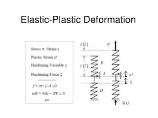
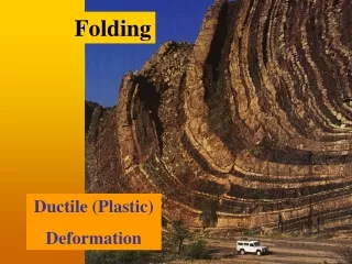
Lec 26 26/03/2014. Plastic deformation and creep in crystalline materials Chap. 11. Mechanical Properties of Materials. Stiffness. Resistance to elastic deformation. Young’s modulus. Strength. Resistance to plastic deformation. Yield stress. Toughness. Resistance to fracture.

E N D
Lec 26 26/03/2014 Plastic deformation and creep incrystalline materials Chap. 11
Mechanical Properties of Materials Stiffness Resistance to elastic deformation Young’s modulus Strength Resistance to plastic deformation Yield stress Toughness Resistance to fracture Energy to fracture ductility Ability to deform plastically Strain to fracture
Uniaxial Tensile Test (Experiment 6) Gaugelength specimen
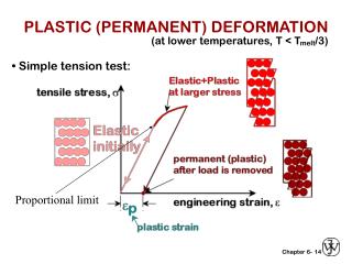
Result of a uniaxial tensile test STRENGTH (Engineering stress) necking Ultimate tensile strength UTS Yield point plastic Yield strength y break elastic Area = Toughness STIFFNESS Slope = Young’s modulus (Y) DUCTILITY f(strain to fracture) (engineering strain)
If there is a smooth transition from elastic to plastic region (no distinct yield point) then 0.2 % offset proof stress is used
During uniaxial tensile test the length of the specimen is continually increasing and the cross-sectional area is decreasing. True stress ≠ Engineering stress (=F/A0) True strain ≠ Engineering strain (=L/L0) True stress Ai = instantaneous area Eqn. 11.3 True incremental strain True strain Eqn. 11.4
Eqn. 11.5 K Strength coefficient n work hardening exponent
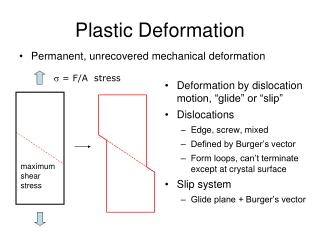
What happens during plastic deformation? • Externally, permanent shape change begins at sy • Internally, what happens?
? What happens to crystal structure after plastic deformation? Plastic Deformation
Some Possible answers Becomes random or amorphous Changes to another crystal structure Remains the same
How Do We Decide? X-ray diffraction No change in crystal structure! No change in internal crystal structure but change in external shape!!
How does the microstructure of polycrystal changes during plastic deformation? EXPERIMENT 5 Comparison of undeformed Cu and deformed Cu
SlipLines Before Deformation After Deformation
Callister Slip lines in the microstructure of plastically deformed Cu Experiment 5
Slip Planes, Slip Directions, Slip Systems Slip Plane: Crystallographic planes Slip Direction: Crystallographic direction Slip System: A combination of a slip plane and a slip direction
Slip Systems in Metallic Crystals Crystal Slip Slip Slip Plane Direction Systems FCC {111} <110> 4x3=12 (4 planes) (3 per plane) BCC{110} <111> 6x2=12 (6 planes) (2 per plane) HCP {001} <100> 3x1=3 (1 plane) (3 per plane)
Why slip planes are usually close packed planes? Why slip directions are close-packed directions?
Slip Systems in FCC Crystal (111) z y x
Tensile vs Shear Stress • Plastic deformation takes place by slip • Slip requires shear stress • Then, how does plastic deformation take place during a tensile test?
1 2 s s: Applied tensile stress N: Slip plane normal D: Slip direction N D F1: angle between s and N F2=angle between s and D Is there any shear stress on the slip plane in the slip direction due to the applied tensile stress? s
f1 2 Resolved Shear stress F = F/ A Area=A FD = F cos2 N As = A cos1 D Area = As F
F F No resolved shear stress on planes parallel or perpendicular to the stress axis F F cos 2 = 0 cos 1 = 0
Plastic deformation recap No change in crystal structure: slip twinning Slip takes place on slip systems (plane + direction) Slip planes usually close-packed planes Slip directions usually close-packed direction Slip requires shear stress In uniaxial tension there is a shear component of tensile stress on the slip plane in the slip direction: RESOLVED SHEAR STRESS
s N D 1 2 s CRITICAL RESOVED SHEAR STRESS
If we change the direction of stress with respect to the slip plane and the slip direction cos 1 cos 2 will change. To maintain the equality which of the following changes takes place? 1. CRSS changes. 2. y changes Schmid’s Law:CRSS is a material constant.
Anisotropy of Yield Stress Yield stress of a single crystal depends upon the direction of application of load cos 1 cos 2 is called the Schmid factor
Active slip system Slip system with highest Schmid factor is the active slip system
Magnitude of Critical Resolved Shear Stress Theory (Frenkel 1926) Experiment
Potential energy Shear stress CRSS b b/2 b d
Critical Resolved Shear Stress Theory (GPa) 12 7 5 Experiment (MPa) 15 0.5 0.3 Ratio Theory/Exp 800 14,000 17,000 Fe (BCC) Cu (FCC) Zn (HCP)
Solution 1934 • E. Orowan • Michael Polanyi • Geoffrey Ingram Taylor
Solution • Not a rigid body slip • Part slip/ part unslipped
Slip Not-yet-slipped Boundary between slipped and unslipped parts on the slip plane Dislocation Line (One-Dimensional Defect)
Movement of an Edge Dislocation From W.D. Callister Materials Science and Engineering
Plastic Deformation Summary • Plastic deformation slip • Slip dislocations • Plastic deformation requires movement of dislocations on the slip plane
Recipe for strength? Remove the dislocation
Stress, MPa Fig. 11.6 700 50 strain Cu Whiskers tested in tension
Lec 29 02.04.2014 crystal structure changes? No Mechanism of deformation slip Nature of stress required for slip Shear stress Is there shear during tension? Resolved shear stress Resolved shear stress required for initiating slip Critical resolved shear stress CRSS is independent of the direction of application of tensile stress
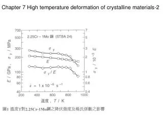
Fe W Al2O3 Si 18-8 ss Ni Cu Effect of temperature on dislocation motion Higher temperature makes the dislocation motion easier Yield stress Eqn. 11.14 11.15 11.16 11.17 11.18 Fig. 11.8 T/Tm 0 0.7