Download

1 / 41
870 likes | 1.82k Vues
Materials at High temperature , Creep. Materials at High Temperature. Microstructure Change – Stability of Materials Grain growth Second-phase coarsening Increasing vacancy density Mechanical Properties Change Softening Increasing of atoms mobility

E N D
Materials at High Temperature Microstructure Change – Stability of Materials Grain growth Second-phase coarsening Increasing vacancy density Mechanical Properties Change Softening Increasing of atoms mobility Increasing of dislocations mobility (climb) Additional slip systems
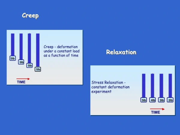
Time-dependent Mechanical Behavior - Creep Creep:Atime-dependent and permanent deformation of materials when subjected to a constant load at a high temperature (> 0.4 Tm). Examples: turbine blades, steam generators.
Creep Curve Typical creep curve under constant load
Creep Curve 1. Instantaneous deformation, mainly elastic. 2. Primary/transient creep. Slope of strain vs. timedecreases with time: work-hardening 3. Secondary/steady-state creep. Rate of straining isconstant: balance of work-hardening and recovery. 4. Tertiary. Rapidly accelerating strain rate up to failure:formation of internal cracks, voids, grain boundaryseparation, necking, etc.
Creep Curve – Constant Stress Comparison between constant load and constant stress
Parameters of Creep Behavior The stage secondary/steady-state creep is of longestduration and the steady-state creep rateis the most important parameter of the creep behaviorin long-life applications. Another parameter, especially important in short-life creepsituations, is time to rupture, or the rupture lifetime, tr.
By plotting the log of the steady creep-rate ss, against log (stress, ), at constant T, in creep curve, we can establish ss = Bn Power-Law Creep Where n, the creep exponent, usually lies between 3 and 8. This sort of creep is called “power-law” creep.
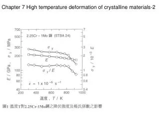
Creep: Stress and Temperature Effects • With increasing stress or temperature: • The instantaneous strain increases • The steady-state creep rate increases • The time to rupture decreases
Creep: Stress and Temperature Effects The stress/temperature dependence of the steady-statecreep rate can be described by where Qc is the activation energy for creep, K2is the creep resistant, and n isa material constant. (Remember the Arrhenius dependence on temperature for thermally activated processes that we discussed for diffusion?)
Larson-Miller Plot Extrapolate low-temperature data from fast high-temperature tests
Creep Relaxation Creep Relaxation: At constant displacement, stress relaxes with time.
tot = el + cr (1) But el = /E (2) and (at constant temperature) cr = Bn (3) Since tot is constant, we can differentiate (1) with respect to time and substitute the other two equations into it give Creep Relaxation (4)
Creep Relaxation Integrating from = i at t = 0 to = at t = t gives (5) As the time going on, the initial elastic strain i/E is slowly replaced by creep strain, and the stress relaxes.
Creep Damage & Creep Fracture Void Formation and Linkage
Creep Damage & Creep Fracture Damage Accumulation
Creep Damage & Creep Fracture Since the mechanism for void growth is the same as that forcreep deformation (notably through diffusion), it follows that thetime to failure, tf, will follow in accordance with:
Creep Damage & Creep Fracture As a general rule: ss tf = C Where C is a constant, roughly 0.1. So, knowing the creep rate, the life can be estimated.
Creep Damage & Creep Fracture Creep – rupture Diagram
Creep Design • In high-temperature design it is important to make sure: • that the creep strain cr during the design life is acceptable; • that the creep ductility fcr (strain to failure) is adequate to cope with the acceptable creep strain; • that the time-to-failure, tf, at the design loads and temperatures is longer (by a suitable safety factor) than the design life.
Creep Design • Designing metals & ceramics to resist power-law creep • Choose a material with a high melting point • Maximize obstructions to dislocation motion by alloying to give a solid solution and precipitates; the precipitates must be stable at the service temperature • Choose a solid with a large lattice resistance: this means covalent bonding.
Creep Design • Designing metals & ceramics to resist diffusional flow • Choose a material with a high melting point • Arrange that it has a large grain size, so that diffusion distances are long and GBs do not help diffusion much • Arrange for precipitates at GBs to impede GB sliding.
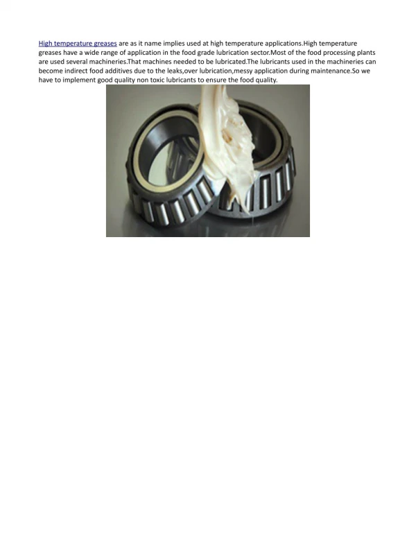
Creep Resist Materials
Case Study – Turbine Blade General Electric TF34 High BypassTurbofan Engine For (1) U.S. Navy Lockheed S-3A anti submarine warfare aircraft (2) U.S. Air Force Fairchild Republic A-10 close support aircraft.
Case Study – Turbine Blade Alloy requirements for turbine blades
Turbine Blade Materials – Nickel-base Superalloys Composition of typical creep-resistant blade
Turbine Blade Materials – Nickel-base Superalloys • Microstructures of the alloy: • Has as many atoms in solid solution as possible ( Co, W, Cr) • (2) Forms stable, hard precipitates of compounds like Ni3Al, Ni3Ti, MoC, TaC to obstruct the dislocations • (3) Forms a protective surface oxide film of Cr2O3 to protect the blade itself from attack by oxygen
Turbine Blade Materials – Nickel-base Superalloys Microstructures of the alloy
Turbine Blade – Development of Processing Investment Casting of turbine blades
Turbine Blade – Development of Processing Directional Solidification (DS) of turbine blades
Turbine Blade – Blade Cooling Air-Cooled Blades