Creep in Materials: Mechanisms, Resistance, and High-Temperature Effects
Explore creep mechanisms, resistance, and high-temperature effects in materials science. Learn about plastic deformation, creep-resistant materials, superplasticity, and designing for high temperatures. Understand the impact of creep on material performance and explore various mechanical metallurgy aspects.

Creep in Materials: Mechanisms, Resistance, and High-Temperature Effects
E N D
Presentation Transcript
MATERIALS SCIENCE & ENGINEERING Part of A Learner’s Guide AN INTRODUCTORY E-BOOK Anandh Subramaniam & Kantesh Balani Materials Science and Engineering (MSE) Indian Institute of Technology, Kanpur- 208016 Email:anandh@iitk.ac.in, URL:home.iitk.ac.in/~anandh http://home.iitk.ac.in/~anandh/E-book.htm CREEP • Review of plastic deformation and failure • Creep Mechanisms (and Maps) • Creep Resistant Materials • Creep in Nanomaterials • Superplasticity • Superplascity in Nanomaterials Mechanical Metallurgy George E Dieter McGraw-Hill Book Company, London (1988)
Review If failure is considered as change in desired performance*- which could involve changes in properties and/or shape; then failure can occur by many mechanisms as below. Mechanisms / Methods by which a can Material can FAIL Elastic deformation Chemical /Electro-chemicaldegradation Creep Physicaldegradation Fatigue Plastic deformation Fracture Microstructuralchanges Twinning Wear Slip Twinning Erosion Corrosion Phase transformations Oxidation Grain growth Particle coarsening * Beyond a certain limit
Review Though plasticity by slip is the most important mechanism of plastic deformation, there are other mechanisms as well (plastic deformation here means permanent deformation in the absence of external constraints): Plastic Deformation in Crystalline Materials Creep Mechanisms Slip(Dislocation motion) Twinning Phase Transformation Grain boundary sliding + Other Mechanisms Vacancy diffusion Grain rotation Dislocation climb Note: Plastic deformation in amorphous materials occur by other mechanisms including flow (~viscous fluid) and shear banding
High-temperature behaviour of materials • Designing materials for high temperature applications is one of the most challenging tasks for a material scientist. • Various thermodynamic and kinetic factors tend to deteriorate the desirable microstructure. This is because kinetics of underlying processes (like diffusion) are an exponential function of temperature. Hence, a small increase in temperature can prove to be ‘catastrophic’. • Strength decreases at high temperature and material damage (e.g. void formation) tends to accumulate. • Phenomena like creep and accelerated oxidation kick-in. • Cycling between high and low temperature will cause thermal fatigue.
High temperature effects (many of the effects described below are coupled) • Increased vacancy concentration at high temperatures more vacancies are thermodynamically stabilized (this will further increase the diffusion rate). • Thermal expansion material will expand and in multiphase materials/hybrids thermal stresses will develop due to differential thermal expansion of the components. • High diffusion rate → diffusion controlled processes become important. • Phase transformations can occur this not only can give rise to undesirable microstructure, but lead to generation of internal stresses.◘ Precipitates may dissolve. • Grain related:◘ Grain boundary weakening may lead to grain boundary sliding and wedge cracking. ◘ Grain boundary migration ◘ Recrystallization / grain growth decrease in strength. • Dislocation related these factors will lead to decrease in strength ◘ Climb ◘ New slip systems can become active ◘ Change of slip system ◘ Decrease in dislocation density. • Overaging of precipitates and precipitate coarsening decrease in strength. • The material may creep (time dependent elongation at constant load/stress). • Enhanced oxidation and intergranular penetration of oxygen. Etc.
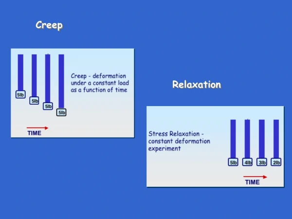
Creep Creep is phenomenological term, which is responsible for plastic deformation. • In some sense creep and superplasticity are related phenomena: in creep we can think of damage accumulation leading to failure of sample; while in superplasticity extended plastic deformation may be achieved (i.e. damage accumulation leading to failure is delayed). • Creep is permanent deformation (plastic deformation) of a material under constant load (or constant stress) as a function of time. (Usually at ‘high temperatures’ → lead creeps at RT). • Normally, increased plastic deformation takes place with increasing load (or stress) • In ‘creep’ plastic strain increases at constant load (or stress) • Usually appreciable only at T > 0.4 Tm High temperature phenomenon. • Mechanisms of creep in crystalline materials is different from that in amorphous materials. Amorphous materials can creep by ‘flow’. • At temperatures where creep is appreciable various other material processes may also active (e.g. recrystallization, precipitate coarsening, oxidation etc.- as considered before). • Creep experiments are done either at constant load or constant stress and can be classified based on Phenomenology or underlying Mechanism. Phenomenology Constant load (easier) Creep can be classified based on Harper-Dorn creep Creep tests can be carried out at Power Law creep Constant stress Mechanism
Constant load creep curve • In a typical creep test the load and temperature are kept constant and the elongation is monitored with time. The strain (typically engineering strain) computed from the elongation is plotted as function of time. The loads employed are typically below the elastic limit. • Three stages may be observed in such a plot: (i) decreasing rate with time, (ii) approximately constant rate, (iii) increasing rate with time. These stages have to be understood keeping in view underlying mechanisms (& necking in stage-III). • The instantaneous strain seen (0) is the elastic strain, which develops on the application of the load. Measured as strain rate (note that this strain rate is not the one imposed as in UTT, but the one which develops in the material) Stages of creep Constant load creep curve Stage-I • Creep rate decreases with time. • Effect of work hardening more than recovery. II I III A technical term Stage-II • Stage of minimum creep rate → ~ constant. • Work hardening is balanced by recovery. Strain ()→ • The distinguishability of the three stages strongly depends on T and Stage-III • Absent (/delayed very much) in constant stress tests (shown later). • Necking of specimen starts in this stage. • Specimen failure processes set in. 0→ Initial instantaneous strain 0 t →
Constant Stress creep curve • In stage-III (due to necking) the engineering stress is no longer a correct measure of the state of stress. To keep the stress constant, the instantaneous area has to be taken into account. • If this is done, then the increasing strain rate part is not observed. Note: if load is kept constant then in stage-III the stress is actually increasing (for the material it is stress which matters and not load). II I Strain ()→ III t →
Effect of stress on the creep curve (constant load) • On increasing the load at which the experiment is conducted: (i) the instantaneous strain (elastic) increases, (ii) for a given time (say t1) the strain is more, (iii) the time to failure (tf) decreases (i.e. as expected, specimens fail earlier). Fracture Elastic strains Strain ()→ → Increasing stress With increasing load there is increased initial elastic strain → 0 increases t → t1
Effect of temperature • On increasing the temperature at which the experiment is conducted: (i) the instantaneous strain (elastic = 0) increases (slightly), (ii) for a given time (say t1) the strain is more, (iii) the time to failure (tf) decreases. • The instantaneous strain 0 increases with increasing T because of the slight decrease in the Young’s modulus (E) of the material. Strain ()→ E↓ as T↑ Increasing T → As decrease in E with temperature is usually small the 0 increase is also small 0 increases → 0 t1 t →
Creep Mechanisms of crystalline materials • Stress and temperature are the two important variables, which not only affect the creep rate, but also the mechanism operative. Three kinds of mechanisms are operative in creep:1dislocation related, 2diffusional, 3grain boundary sliding. These and their sub-classes are shown in the next page. • At high temperatures the grain boundary becomes weaker than the grain interior and two grains can slide past one another due to shear stress. The temperature at which the grain is as strong as the grain boundary is called the equicohesive temperature. • A combination of these mechanisms could also be responsible for the creep strain. • Depending on the stress and temperature other mechanisms of plastic deformation or microstructural changes may occur concurrently with creep. These include plastic deformation by slip and dynamic recrystallization. • Deformation mechanism maps can be drawn with homologous temperature (T/Tm) and normalized shear stress (/G) as the axis (other combination of variables may also be chosen for these plots: T/Tm vs shear strain rate, normalized shear stress vs shear strain rate, etc.). Typically these maps overlay descriptors, which are based both on phenomenology and mechanism.
Creep Mechanisms of crystalline materials Cross-slip Climb Dislocation related Glide Coble creep Grain boundary diffusion controlled Creep Diffusional Nabarro-Herring creep Lattice diffusion controlled Dislocation core diffusion creep Diffusion rate through core of edge dislocation more Interface-reaction controlled diffusional flow Grain boundary sliding Accompanying mechanisms: creep with dynamic recrystallization
Creep Mechanisms of crystalline materials Cross-slip Harper-Dorn creep Climb Dislocation related Glide Coble creep Creep Grain boundary diffusion controlled Nabarro-Herring creep Diffusional Lattice diffusion controlled Dislocation core diffusion creep Diffusion rate through core of edge dislocation more Interface-reaction controlled diffusional flow Grain boundary sliding Accompanying mechanisms: creep with dynamic recrystallization
Dislocation related mechanisms • Two roles can be differentiated with respect to of dislocations activity: (i) it is the primary source of strain, (ii) it plays a secondary role to accommodate local strain (while the major source of strain is another mechanism (e.g. grain boundary sliding). Cross-slip • This kind of creep is observed at relatively low temperatures. Herein screw dislocations cross-slip by thermal activation and give rise to plastic strain as a function of time. Dislocation climb • Edge dislocations piled up against an obstacle can climb to another slip plane and cause plastic deformation. In response to stress this gives rise to strain as a function of time. It is to be noted that at low temperatures these dislocations (being pinned) are sessile and become glissile only at high temperatures. • Rate controlling step is the diffusion of vacancies.
Nabarro-Herring creep → high T → lattice diffusion Diffusional creep Coble creep → low T → Due to GB diffusion • In response to the applied stress vacancies preferentially move from surfaces/interfaces (GB) of specimen transverse to the stress axis to surfaces/interfaces parallel to the stress axis→ thus causing elongation. • Diffusion of vacancies in one direction can be thought of as flow of matter in the opposite direction. • This process like dislocation creep (involving climb) is controlled by the diffusion of vacancies (but diffusional creep does not require dislocations to operate). • The diffusion could occur predominantly via the lattice (at high temperatures) or via grain boundaries (at low temperatures). The former is known as Nabarro-Herring creep, while the later is known as Coble creep. • Diffusion through edge dislocation cores (pipe diffusion) could play an important role in creep. Flow of vacancies
Grain boundary sliding • At low temperatures the grain boundaries are ‘stronger’ than the crystal interior and impede the motion of dislocations. • Being a higher energy region, the grain boundaries may pre-meltbefore the crystal interior. • Above the equicohesive temperature, due to shear stress at the ‘local scale’, grain boundaries slide past one another to cause plastic deformation. • The relative motion of grain boundaries can lead to wedge cracks at triple lines (junction of three grains). If these wedge cracks are not healed by diffusion (or slip), microstructural damage will accumulate and will lead to failure of the specimen. Grains Wedge crack due to grain boundary sliding
Phenomenological descriptions of creep • One of the important descriptions of creep is using the power-law formula. The shear strain rate is a power function of the shear stress. Clearly this formula is not based on a mechanism operative, but a fit of data. Power-law behaviour can arise from: • Only glide at low temperatures (~0.3TM). Here the exponent n ~ 3. • Glide + climb (referred to as climb controlled creep) occurs at higher temperatures. Above ~0.6TM climb is lattice-diffusion controlled. At lower temperatures than this pipe diffusion may play an important role in creep. • At high stresses (> 103G) the power law breaks down. At high stresses the mechanism changes from climb controlled (creep) to glide controlled (slip). This is bordering on normal plastic deformation.
Deformation Mechanism Maps • Time and temperature are coupled when it comes to processes like diffusion. • At large values of stresses and at low T, the time ‘available’ is less (as material ‘immediately’ begins to deform plastically) and creep mechanisms do not have time (/activation) to operate. • Usually contours of constant strain rate are superimposed on these diagrams (not shown here). Stress or strain rate can be used as axes (variable). In components (e.g. truss in a structure, pressure vessel, etc.) stress is ‘prescribed’, while in processing (e.g. extrusion, forging, etc.), strain rate is ‘prescribed’. At high stresses plastic flow will take place The dominant mechanism is shown in the diagram Dynamic recrystallization gives rise to ‘strain-free’ grains. At high temperature and low stress Diffusional creep dominates From “Deformation Mechanism Maps: The plasticity and creep of Metals and Ceramics” by H.J. Frost and M.F.Ashby, Pergamon Press, Oxford, 1982.
From “Deformation Mechanism Maps: The plasticity and creep of Metals and Ceramics” by H.J. Frost and M.F.Ashby, Pergamon Press, Oxford, 1982.
Creep Resistant Materials • The is a growing need for materials to operate at high temperatures (and in some applications for long times). For example, higher operating temperatures gives better efficiency for a heat engine. Hence, there is a need to design materials which can withstand high temperatures. • It is to be noted that material should also be good in other properties for high temperature applications (like it should possess good oxidation resistance). Factors like cost, ease of fabrication, density, etc. play an important role in determining the final choice of a material. • Some of the material design strategies, which work at low temperature are not useful at high temperatures (e.g. work hardening, precipitation hardening with precipitates which coarsen, grain size reduction, etc.). • Some strategies which work are: (i) having grain boundaries aligned along the primary loading axis, (ii) produce single crystal components (like turbine blades), (iii) use precipitates with low interfacial energy for strengthen (which will not coarsen easily), (iv) use dispersoids for strengthening. High melting point → E.g. Ceramics Creep resistance Dispersion hardening → ThO2 dispersed Ni (~0.9 Tm) Solid solution strengthening Single crystal / aligned (oriented) grains
Creep Resistant Materials, cotd.. • Commonly used materials → Fe, Ni (including superalloys), Co base alloys. • Precipitation hardening involving ‘usual precipitates*’ is not a good method as precipitates coarsen (smaller particles dissolve and larger particles grow interparticle separation ↑ thus lowering the strength) • Ni-base superalloys have Ni3(Ti,Al) precipitates, which form a low energy interface with the matrix. This reduces the driving force for coarsening. (Note: other phenomena like rafting may lead to the deterioration of the properties of such materials). • Cold work cannot be used for increasing creep resistance, as recrystallization can occur which will produced strain free crystals. • Fine grain size is not desirable for creep resistance (this is contrary to what is usually practiced for increasing the low temperature strength)→ grain boundary sliding can cause creep elongation/cavitation. Hence, the following two strategies can be used:► Use single crystals (single crystal Ti turbine blades in gas turbine engine have been used though they are very costly).► Aligned/oriented polycrystals → as all the grain boundaries are aligned along the primary tensile axis, they experience no shear stress and creep is negated. * Which coarsen at high temperatures due to high interfacial energy.
Creep in Nanomaterials • Due to fine grain size nanostructured materials (grain size in the nanoscale regime) are expected to: (i) show creep at relatively lower temperatures, (ii) display higher creep rates for a give temperature, (iii) experience predominance of mechanisms like grain boundary diffusion and grain boundary sliding. We now see what is actually seen in experiments. • In nanocrystalline Pd (~40 nm) and Cu (~20 nm), there seemed to be no increase in creep rate as compared to micron grain sized materials (in some temperature regimes even a lower creep rate was observed for Pd). This is in direct contradiction with the expectation that nanocrystalline materials will experience a higher creep rate. Studies on Cu (10-25 nm GS), Pd (35-55 nm GS) (TEM showed porocity in sample) [1] creep in the low T regime (0.24-0.33 Tm) → low creep rate, low grain growth creep in the medium T regime (0.33-0.48 Tm) → creep rate decreasing even after long testing time, grain growth (25 nm → 100s of nm) • Cu creep rates of nc sample was comparable to micron GS sample • Pd nc sample exhibited lower creep rates [1] P.G. Sanders, M. Rittner, E. Kiedaisch, J.R. Weertman, H.Kung, Y.C. Lu, Nanostruct. Mater. 9 (1997) 433. [2] D.L. Wang, Q.P. Kong, J.P. Shui, Scr. Metall. Mater. 31 (1994) 47.
In some cases the creep rate increased with a decrease in grain size in the nanoscale regime of grain sizes (e.g. in Ni-P nanocrystalline material the creep rate of ~30 nm grain sized material was higher than that of 250 nm material [2]). • In cases where high creep rate expected for nanocrystalline materials (e.g. Pd, Cu) was not observed, the reason attributed are: (i) presence of low angle grain boundaries and twin boundaries (which are not prone to sliding and have low diffusivity for vacancies), (ii) reduced dislocation activity in nanocrystalline samples.
Creep of nc-Ni at RT (GS: 6, 20, 40 nm) [1]: Smaller grain size (6nm) showed faster creep rate. Behaviour consistent with Grain boundary sliding controlled by grain boundary diffusion mechanism. At high stresses and larger GS (20, 40 nm), dislocation creep was observed. [1] N. Wang, Z. Wang, K.T. Aust, U. Erb, Mater. Sci. Eng., A 237 (1997) 150.
Superplasticity • The phenomenon of extensive plastic deformation without necking is termed as structural superplasticity. Superplastic deformation in tension can be >300% (up to even 2000%). • Typically superplastic deformation occurs when: (i) T > 0.5Tm(ii) grain size is < 10 m(iii) grains are equiaxed (which usually remain so after deformation)(iv) grain boundaries are glissile (with a large fraction of high angle grain boundaries). • Presence of a second phase (of similar strength to the matrix- reduces cavitation during deformation), which can inhibit grain growth at elevated temperatures helps (e.g. Al-33%Cu, Zn-22% Al)). • Many superplastic alloys have compositions are close to eutectic or eutectoid points. • Superplastic flow is diffusion controlled (can be grain boundary or lattice diffusion controlled).
A plot of stress versus strain rate is often sigmoidal and shows three regions: • Region-I- low stress, low strain rate regime ( <105 /s) m (0.2,0.33) Sensitive to the purity of the sample. Lower ductility and grain boundary diffusion. • Region-II- intermediate stress & strain rate regime [ (10–5, 10–2)] m (0.4,0.67)Extended region covering several orders of magnitude in strain rate. Region of maximum ductility. Strain rate insensitive to grain size and insensitive to purity. Often referred to as the superplastic region.Mechanism predominantly grain boundary sliding accommodated by dislocation activity (Activation energy (Q) corresponding to grain boundary diffusion (Qgb)). • Region-III- high stress & strain rate regime ( > 102 /s) m > 0.33Creep rates sensitive to grain size. Mechanism intragranular dislocation process (interacting with grain boundaries). Note: low ‘m’ in region I and III
Superplasticity in Nanomaterials • In most cases the superplasticity has not fulfilled the initial ‘expectations’. • In many cases superplasticity is only observed in nanocrystalline samples, where it is already observed in their microcrystalline counterparts. • Superplasticity was observed in nanocrystalline Ni (20 nm grain size) at 0.36Tm(more than 450C lower than that for the bulk material) [1]. • Nanocrystalline Ni3Al (grain size 50 nm) also became superplastic about 450C below its microcrystalline counterparts. Ni3Al had a ductility of 350% at 650C (strain rate of 10–3 /s). • 1420-Al alloy showed superplasticity at a high strain rate of 10–1 /s. High amount work hardening and higher flow stress for superplastic deformation as compared to micron grain sized material is observed in these cases. • Superplasticity was observed in ~40 nm grain size Zn-Al alloy at 373 K, tested at a strain rate of 10–4 /s [2]. Microcrystalline samples showed no superplasticity! Ni3Al (cP4, Pm-3m) [1] S. X. McFadden, R. S. Mishra, R. Z. Valiev, A. P. Zhilyaev and A. K. Mukherjee, Nature 398 (1999) 684. [2] R.S. Mishra, R.Z. Valiev, A.K. Mukherjee, Nanostruct. Mater. 9 (1997) 4732.
Superplasticity at low temperature (or equivalently Superplasticity at high strain rates (> 10–2 /s) at a given temperature in the superplastic regime) is caused by: increased diffusion, grain boundary sliding and dislocation activity. • Grain growth is a serious issue during superplasticity experiments. In the case of nc-Ni it was seen that the grain size could increase to micron sizes, from the starting grain size of the order of 20 nm. In other materials the grain growth could be less. Grain growth is expected to be less is two phase mixtures (2nd phase as a precipitate preferred) and intermetallic compounds. In two phase mixtures the 2nd phase has a pinning effect on the grain boundaries; while in intermetallics (like Ni3Al) order (with respect to the sublattices) has to be maintained during grain growth, which restrains the process. • In cases where grain boundary sliding is the predominant mechanism for superplasticity (e.g. in some Mg alloys), it is seen that non-equilibrium grain boundaries give lower elongation as compared to equilibrium grain boundaries (due to the long range stress fields associated with non-equilibrium grain boundaries, which is expected to hamper grain boundary sliding). • In Ni3Al the high flow stresses and extensive strain hardening during superplastic deformation has been attributed to depletion of dislocations and high stresses required for the nucleation of new ones [1]. [1] R.S. Mishra, R.Z. Valiev, S.X. McFadden, A.K. Mukherjee, Mater. Sci. Eng., A 252 (1998) 174.