Instrumentation at CLS
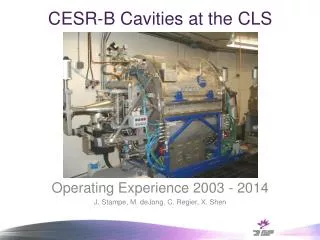
Instrumentation at CLS. Elder Matias Canadian Light Source University of Saskatchewan 2001-10-20. CLS Control System. More than 100 computers Mix of technologies (including industrial control hardware and scientific data acquisition hardware)

Instrumentation at CLS
E N D
Presentation Transcript
Instrumentation at CLS Elder Matias Canadian Light Source University of Saskatchewan 2001-10-20
CLS Control System • More than 100 computers • Mix of technologies (including industrial control hardware and scientific data acquisition hardware) • Software based on a system called EPICS that was originally developed for Star Wars. Today EPICS is used to control synchrotrons, accelerator facilities and radio telescopes around the world.
CLS Control System (cont.) • The computer hardware is interconnected over a mix of Ethernet and Profibus. • The control system measures and controls several thousand signals, e.g., • Position of the beam in the storage ring to within 1 m • Magnet set points and feedback values • Temperature sensors, valves, flow switches ... • All of this data is acquired and logged in real-time.
Transition Radiation Monitors • Non-destructive method of obtaining beam profile information • A thin aluminized Mylar foil is moved into the beam • Transition radiation is produced as the beam passes through the foil • We are working on capturing a video image of the beam, determining the position and shape of the beam and then readjusting steering elements in the accelerator.
Orbit Correction System • The beam orbit in the storage ring must be maintained within 1m and the orbit corrected at approx. 100 Hz. • The position of the beam is monitored to within 1m at 56 monitor stations within the storage ring. • Orbit corrector magnets are used to correct the beam position.
Vibration Monitor Position of the experiment stable to 1m? • Internal Vibration Sources • Pumps, compressors, fans ... • Ramping of the booster • Crane, forklift, people walking ... • External Vibration Sources • Trucks, trains, planes • Wind on building walls • Ocean surf ? Separate concrete slabs for building, booster, storage ring/ beamlines. How well do the isolation joints in the floor isolate the slabs?
Vibration Monitor (cont.) • A portable vibration monitoring system was developed to measure building vibration and displacement. • Custom software to acquire the data and analyse the data is under development.
Vibration Monitor (cont.) PXI-6052E SCXI-1531 PXI-1010 Mainframe Computer SCXI-1349 Accelerometer PXI-PCI 8335 MXI-3 with fiber cable, up to 200 m long PXI-6052E SCXI-1531 PXI-1010 Mainframe SCXI-1349 Accelerometer
Vibration Monitor (cont.) 2 2 Acceleration [μm/s ] Acceleration Spectrum [μm/s ] 8 10 0 -8 0 0 0 2 4 6 Time [s] 100 200 300 Displacement [μm] Frequency [Hz] 2 0 -2 0 2 4 6 Time [s]