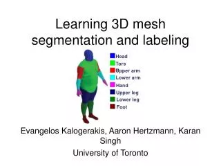
3D Head Mesh Data
3D Head Mesh Data. Stereo Vision Active Stereo 3D Reconstruction 3dMD System. Data Types. Volumetric Data Voxel grids Occupancy Density Surface Data Point clouds Range images (range maps). Range Acquisition Taxonomy. Mechanical (CMM, jointed arm).

3D Head Mesh Data
E N D
Presentation Transcript
3D Head Mesh Data • Stereo Vision • Active Stereo • 3D Reconstruction • 3dMD System
Data Types • Volumetric Data • Voxel grids • Occupancy • Density • Surface Data • Point clouds • Range images (range maps)
Range Acquisition Taxonomy Mechanical (CMM, jointed arm) Inertial (gyroscope, accelerometer) Contact Ultrasonic trackers Magnetic trackers Industrial CT Rangeacquisition Transmissive Ultrasound MRI Radar Non-optical Sonar Reflective Optical
Range Acquisition Taxonomy Shape from X: stereo motion shading texture focus defocus Passive Opticalmethods Active variants of passive methods Stereo w. projected texture Active depth from defocus Photometric stereo Active Time of flight Triangulation
Optical Range Scanning Methods • Advantages: • Non-contact • Safe • Usually inexpensive • Usually fast • Disadvantages: • Sensitive to transparency • Confused by specularity and interreflection • Texture (helps some methods, hurts others)
Stereo • Find feature in one image, search along epipole in other image for correspondence
Depth Perception from StereoSimple Model: Parallel Optic Axes image plane z Z f camera L xl b baseline f camera R xr x-b X P=(x,z) y-axis is perpendicular to the page. z x-b f xr z x f xl z y y f yl yr = = = =
Resultant Depth Calculation For stereo cameras with parallel optical axes, focal length f, baseline b, corresponding image points (xl,yl) and (xr,yr) with disparity d: This method of determining depth from disparity is called triangulation. z = f*b / (xl - xr) = f*b/d x = xl*z/f or b + xr*z/f y = yl*z/f or yr*z/f
Epipolar Geometry Constraint:1. Normal Pair of Images The epipolar plane cuts through the image plane(s) forming 2 epipolar lines. P z1 y1 z2 y2 epipolar plane P1 x P2 C1 C2 b The match for P1 (or P2) in the other image, must lie on the same epipolar line.
Epipolar Geometry:General Case P y1 y2 P2 x2 P1 e2 e1 x1 C1 C2
Constraints 1. Epipolar Constraint: Matching points lie on corresponding epipolar lines. 2. Ordering Constraint: Usually in the same order across the lines. P Q e2 e1 C1 C2
Finding Correspondences • If the correspondence is correct, triangulation works VERY well. • But correspondence finding is not perfectly solved. • For some very specific applications, it can be solved • for those specific kind of images, e.g. windshield of a • car where the opening shows up as a clear horizontal line. • General passive stereo matching is not precise enough for • the head meshes used at Children’s Research Institute.
Shape from Motion • Track a feature in a video sequence • For n frames and f features, have2nfknowns, 6n+3f unknowns • Solve for the 3D parameters
Shape from Motion • Advantages: • Feature tracking easier than correspondence in far-away views • Mathematically more stable (large baseline) • Disadvantages: • Does not accommodate object motion • Still problems in areas of low texture, in non-diffuse regions, and around silhouettes
Shape from Shading • Given: image of surface with known, constant reflectance under known point light • Estimate normals, integrate to find surface • Problems: most real images don’t satisfy the assumptions; there is ambiguity in the process
Shape from Shading • Advantages: • Single image • No correspondences • Analogue in human vision • Disadvantages: • Mathematically unstable • Can’t have texture • Not really practical • But see photometric stereo
Active Optical Methods • Advantages: • Usually can get dense data • Usually much more robust and accurate than passive techniques • Disadvantages: • Introduces light into scene (distracting, etc.) • Not motivated by human vision
Active Variants of Passive Techniques • Regular stereo with projected texture • Provides features for correspondence • Active depth from defocus • Known pattern helps to estimate defocus • Photometric stereo • Shape from shading with multiple known lights
What Kinds of Patterns • Most common: light stripes • Variation: colored light stripes • Variation: grids of light stripes • Variation: point patterns
Multiple Stripes • Project multiple stripes • But which stripe is which? • Answer #1: assume surface continuity
Colored Multiple Stripes • To go faster, project multiple stripes • But which stripe is which? • Answer #2: colored stripes (or dots)
3D ReconstructionColor Images Perform point matching; obtain depth images.
Depth Images Use the depth, plus the direction from which each image was taken to carve out 3D space to find the object.
Space Carving All of 3D space is made up of cubes. Use the known location of each cubes and known depth values in each image of the object to decide if the cube is behind, in front of, or part of the object.
Space Carving Case 1: cube in front of object Case 2: cube behind object Case 3: cube on boundary
Space Carving Algorithm • for each level of cube resolution from large to small • for each cube in 3D space at this resolution • if the cube lies in front of the object for any camera • carve it away • if the cube lies behind the object for all cameras • make it part of the object • else call it on the boundary of the object at this level • and go on to the next finer level of resolution
From Voxels to 3D Mesh • Space carving leaves us with a voxel representation. • Medical imaging modalities also give us a voxel representation. • We can work with voxels, but it is often more convenient to • convert to a 3D triangular mesh as is used in graphics. • The most common algorithm for producing a mesh from a • voxel representation is the Marching Cubes algorithm.
Marching Cubes Marching Cubes is an algorithm which “creates triangle models of constant density surfaces from 3D medical data.”
What does that mean? Medical Data + Marching Cubes = Pretty Pictures = Visualization
Visualization Process • Medical Data Acquisition • Image Processing • Surface Construction • Display
Medical Data Acquisition • Computed Tomography (CT) • Magnetic Resonance (MR) • Single-Photon Emission Computed Tomography (SPECT) Each scanning process results in two dimensional “slices” of data.
Surface Construction • Construction/Reconstruction of scanned surfaces or objects. • Problem of interpreting/interpolating 2D data into 3D visuals. • Marching Cubes provides a new method of creating 3D surfaces.
Marching Cubes Explained • High resolution surface construction algorithm. • Extracts surfaces from adjacent pairs of data slices using cubes. • Cubes “march” through the pair of slices until the entire surface of both slices has been examined.
Marching Cubes Overview • Load slices. • Create a cube from pixels on adjacent slices. • Find vertices on the surfaces. • Determine the intersection edges. • Interpolate the edge intersections. • Calculate vertex normals. • Output triangles and normals.
How Are Cubes Constructed • Uses identical squares of four pixels connected between adjacent slices. • Each cube vertex is examined to see if it lies on or off of the surface.
How Are The Cubes Used • Pixels on the slice surfaces determine 3D surfaces. • 256 surface permutations, but only 14 unique patterns. • A normal is calculated for each triangle vertex for rendering.
Triangle Creation • Determine triangles contained by a cube. • Determine which cube edges are intersected. • Interpolate intersection point using pixel density. • Calculate unit normals for each triangle vertex using the gradient vector.
Improvements Over Other Methods • Utilizes pixel, line and slice coherency to minimize the number of calculations. • Can provide solid modeling. • Can use conventional rendering techniques and hardware. • No user interaction necessary. • Enables selective displays. • Can be used with other density values.
Characteristics • multiple cameras take color photos • active stereo using a point pattern for mathing • rapid image acquisition: 1.5 ms. • high precision: accurate to within .2mm RMS • accurate texture mapping of color photos to mesh • supports multiple file formats • used in hospitals, clinics, medical research institutes • used at both Seattle Children’s Hospital and • Children’s Research Institute
Promotional Video 3dMD System Demo
The “us” Database Dingding Indri Kasia Sara Steve EricJia Linda Shulin Xiang