TIU Tracking System
TIU Tracking System. Capstone 2011 Sponsored by Intel Advisor: Prof. Robert Daasch. Team Members: Daniel Ferguson – Dung Le Lynh Pham – Man Hoang – Tri Truong. Products. Introduction. Design.

TIU Tracking System
E N D
Presentation Transcript
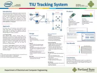
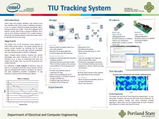
TIU Tracking System • Capstone 2011 • Sponsored by Intel • Advisor: Prof. Robert Daasch • Team Members: • Daniel Ferguson – Dung Le • Lynh Pham – Man Hoang – Tri Truong Products Introduction Design • Intel's large and complex validation labs contain many Testing Interface Unit's(TIU) used in validating hardware. A TIU is a custom PCB that provides test points a testing machine can probe. Since the hardware to be tested is varied, there exists a variety of different TIU's, and as such, finding a particular TIU is useful. This is useful because, previously, the testing machine had to be broken down to identify the TIU it was using • Tags are placed onto Test Interface Units (TIUs). The tags broadcast a signal periodically, which is picked up by detectors that are placed in various fixed locations within the tracking area. The detectors determine the strengths of the signals from the tags, form a message and relay it, via the mesh network of other detectors until the message reaches the proxy. The proxy then retransmits the message via Wi-Fi to the Controller. The Controller gives the signal strength data to a locating algorithm which calculates the tags’ approximate locations via statistical analysis. The results are placed into a database where the Web App periodically retrieves the results and displays them on an interactive 2D map. • Detector • Size: 3.5”x1” • Use ATMega328p MCU • Use 9V battery/adapter • Use RF12B transceiver at 434MHz • Asset Tag • Size: 1”x1”x1” • Use ATMega328p MCU • Use 20mm coin cell battery • Battery life: more than 3 months • Use RF12B transceiver at 434MHz Back-end Front-end Users Admin Requirements Detector • Asset tag’s size: 1” x 1” x 1” • Low power consumption • Accurate • Web application as user interface • The tracking region must scale to at least 10,000 sp ft • Low cost solution Database Tag Wi-Fi Approach Features Our system uses an RF transceiver mesh network to track mobile assets indoors. The system determines an asset’s current location by matching the RF fingerprint, based on signal strength, of a Tags periodic broadcasts with previously collected fingerprints stored in a database. Why signal strength? We based our system on signal strength because it has two important features. Since our system cannot rely on line of sight, RF signals satisfy this requirement. Low power transceivers are available. Radio Received Signal Strength Indication (RSSI) is a measurement of the amount of power received by antenna. Theoretically, distances can be approximated based on the relationship between transmitted and received signal strength. Tags are attached to TIUs. They are the beacon with which locations can be calculated. It is critically important that tags preserve power. Therefore they are typically in a low power state, but periodically wake up to broadcast, and then immediately go back to their low power state. Detectors are responsible for gathering RSSI data for the locating algorithm. They must always be listening for a tag to broadcast. Upon receiving a broadcast from a tag, or another detector, it rebroadcasts the message, which results in messages always propagating toward the proxy. For scalability, a mesh network of detectors relay all data to a centralized controller where locations of tags are calculated and saved in a database. An easy to use web application provides visualization of tag locations, as well as other maintenance details. • Controller • Primary link between the mesh network and the back end infrastructure • Communicates with mesh network • Executes the locating algorithm • Communicates with the Database • RF Mesh Network • Composed of small, inexpensive hardware • Relay messages to the proxy via a controlled flooding mechanism • Collision avoidance using time division • Tags broadcast periodically • Detectors pick up broadcasts, determine signal strengths, and send results • Detectors also act as relays Web App Controller Test Results Proxy • Web Application • Primary user interface • Interactive 2D map • Search TIU and detector via ID • Show battery level of all elements in the mesh network • Configure tag • Configure detector placement • Configure geometry of tracking area • Wi-Fi Proxy • RFM12 module receives data from the mesh network • Wi-Fi module sends data to the controller • Fingerprint Algorithm • A progressively constrained, nearest neighbor algorithm, using Euclidean distance as the matching metric. Also, several heuristics are employed that further enhance the accuracy and reliability of the locating process Conclusions • SQL Database • Stores locations and battery information of all tags and detectors • Stores user accounts • The accuracy of the tracking system needs to be enhanced by considering antenna design and advanced locating algorithm. Noise filter can be implemented on both hardware and software to achieve desired performance. Department of Electrical and Computer Engineering