Data Path
This document provides a confidential general description of the QLM box and the associated data path components within the computer infrastructure of the TPFM rack systems. It explores the functionality of the ILP2000 board, TTLC board, and Advantech I/O systems, highlighting their roles in data processing and printing. Additionally, it outlines the architecture of the TPFM rack, including the arrangement and purpose of various boards dedicated to different color outputs. The document concludes with insights into system indicators, voltage requirements, and troubleshooting functionalities.


Data Path
E N D
Presentation Transcript
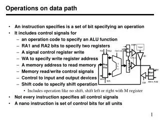
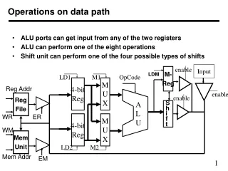
150 flat Cables 15 Drivers 150 IJ Heads K M C Y ML CL K M C Y ML CL Electronics Cabinet Serial data channel BRIDGE Data Channel - General Description Confidential
Computer QLM box 2U TPFM rack I.J Heads I.J Drivers I.J Bus (BP) Printed image Data Flow General Description Confidential
Data Path Components Inside the Computer • ILP2000 Board – Data process board – Reads the image data, which is loaded into the memory by DMA method (Direct Memory Access) without using CPU time, in order to accelerate the process. • TTLC Board – RS422 Transmitter – Receives the data signals from the ILP2000 board and transmits them to the QLM box. • Advantech I/O – Responsible for Communication between the computer’s PCI bus and the MTFM boards (ISA) inside the QLM Box. Confidential
MTFX-QLM Box Confidential
MTFX-QLM Box (Cont.) • The purpose of the QLM box is to serve as ISA to PCI adaptor, since ISA slots are no longer manufactured. • Consists of two MTFM ISA boards and a QLM board. • 32-bit Printing data is “transferred” from the ILP2000 board (via the TTLC Board) to the QLM board. The QLM board interpolates the printing data to 96-bit and sends it to the two MTFM boards, 16-bit per each color. Confidential
MTFX-QLM Box (Cont.) • The “SEND TABLES” command (timer parameters-printing mode and resolution), is sent to the QLM box, which is supplied from Advantech I/O PCI (located inside the computer). See data path functional description. • One board is dedicated for four colors (C, M, Y, K) and the second board for the other two (CL, ML). Confidential
MTFX-QLM Box (Cont.) • Easy to access and service Confidential
2 Colors TPFM 4 Colors To TTLC To I/O MTFX-QLM Box (Cont.) • Rear View Confidential
MTFX-QLM Box (Cont.) Confidential
MTFM- A: Cyan Yellow Black Magenta MTFM- B: Cyan Light Magenta Light MTFX-QLM Box (Cont.) • Inside View Confidential
TPFM Rack • 2U Rack includes the following boards: • First TPFM board for Cyan and Yellow colors • Second TPFM board for Magenta and Black colors • Third TPFM board for Light Cyan and Light Magenta • All boards are easy to access and service Confidential
TPFM Rack (Cont.) • Every TPFM board functions as one TIMER and four PFM’s of PJ. The reason is that the data channel is twice as much as in the PJ machines due to the difference between the IJ heads(96 nozzles in the TJ8300 compared to 48 in the PJ). • All 3 boards are similar and can be swapped easily for troubleshooting. • The following voltages are supplied to the 2U rack: • 12V DC for TPFM boards • 12V DC for I.J drivers • 48V DC for I.J drivers Confidential
Cyan-Yellow Magenta-Black Light Cyan- Light Magenta TPFM Rack (Cont.) • Front Panel Confidential
TPFM Rack (Cont.) • Indication Lights • Over run (Red LED) • Indicates an error that appears when the TPFM board is asking for data but the QLM-MTFX box is not sending any,or any other problem in the data flow. • The over run should be: • Blinking only before initialization (“send tables”). • Off after initialization, which indicates OK status. • Live (Green LED) • Normally blinking, which Indicates FM initialization(after “send tables”). Confidential
TPFM Rack (Cont.) • Indication Lights (Cont.) • CONFDONE • Should be on after “send tables”. • FUNC • Blinking after send tables (before it is off). • JOG • On when the drum is jogging. • START • On as soon as the machine starts to receive data. Confidential
TPFM Rack (Cont.) • Indication Lights (Cont.) • PLOT and FRAME • On during plot. • AMPL • Off during print and ON when the machine is not printing. • AD EN • Auto-drop enabled. Confidential
TPFM Rack (Cont.) • Rear Panel Confidential
12VDC for I.J Drivers JB1=Cyan 12VDC for TPFM boards JB2=Yellow JB4=Black 48VDC for I.J Heads JB3=Magenta JB6=Magenta light JB5=Cyan light TPFM Rack (Cont.) • SCSI 100P data Cables to the back plan boards on the bridge Confidential
J1=Cyan+Yellow J4=Magenta+Black J7=Control J11=Light magenta+Light Cyan J71= Control JC1 To control Unit TPFM Rack (Cont.) • SCSI 68P data Cables to the QLM-MTFX box Confidential
TPFM Rack (Cont.) • Outputs • Timing • LF (line frequency) – Output for the PFM inside theTPFM board • 4 x Frame signals – Two for each color: one for odd and one for even. Output for the PFM inside the TPFM board. • IJ driver pulse width • Enables signals for Iron operation • Auto drop function: • Ink tickling and spitting when the system is not plotting Confidential
TPFM Rack (Cont.) • Inputs • Drum encoder signals – channels A and B • Drum home position sensor • Timer initialization function (“Send Tables” function) Confidential
TPFM Rack (Cont.) • Timer Parameters • Plot mode – Normal/Best • Plot resolution –3 36 (18 rotations) or 448 dpi (24 rotations) • IJ driver pulse width – preset for all colors • IJ driver pulse Amplitude – Must be set from the RT-run software • Iron start and stop position • Drum Auto drop position for all colors Confidential
TPFM Rack (Cont.) • Auto-Drop Operation Modes • When the drum is not moving • Starts 20 seconds after drum stops • 5 KHz tickling • 9.5 µs pulse width (Preset) • Spitting ink every 60-90 seconds for 100 ms • Pulse spitting amplitude can be set from the RT-Run according to ink type Confidential
TPFM Rack (Cont.) • Auto-Drop Operation Modes (Cont.) • When the drum is jogging • 5-10 KHz tickling • 9.5µs pulse width (preset) • Spitting ink every rotation of the drum in theAuto drop groove Confidential
TPFM Rack (Cont.) • Auto-Drop Deactivation Modes • During plot • During ink system macro activation such as: • Standby • Prime • LPAP • During 24V power fail to the CCB • When 48VDC is deactivated from the software • When data power switch in the supply unit is deactivated Confidential
TPFM Rack (Cont.) • TPFM Boards • A total of 3 TPFM boards – each for 2 colors. • Every TPFM board is equal to 4 PFM +1 Timer boards – as in the PJ. • Converts the Raster, 1-bit Tiff data to plot data. Confidential
TPFM Board – Operation Modes • Setup: • For 1-bit Tiff and raster files the color management is performed and inserted during the file RIP in the ONIX RIP station. • Run mode: • Receives timing from the timer, which is an integrated part of the TPFM: • LF clock • Frame • Receives 1-bit Tiff Raster data from QLM-MTFX box. • Transmits plot data towards the bridge (BUS board-IJ driver-IJ heads) with correct timing. Confidential
IJ Drivers • A total of 15 IJ driver boards, which are arranged in 5 columns and 3 rows. • Every 3 IJ drivers are assembled on 1 bus board – a total of 5 bus boards. • Each driver address is set on the bus board – 1st , 2nd , 3rd … • Each board serves 10 IJ heads of two colors, 5 per each. • The pulse width is preset on the board and set to 9.5 µsec. • The pulse height is set to 35VDC by default. Confidential
IJ Drivers (Cont.) • The pulse height is controlled from the RT software and can be set between 28VDC-35VDC for each color separately inside of each IJ driver board. • The IJ driver board for ”E1” heads includes diagnostics features. • The pulse shape is shown in the RT software instead of using oscilloscope as in the past. Confidential
Parallel Data Serial Data Connection between IJ Heads and IJ Drivers Confidential
24 connectors – 50 lead each one 3 connectors – 200 lead each one 20 connectors – 50 lead each one 1800 pins socket 60 cables of 50 conductors to print heads per manifold IJ Boards and IJ Bus Confidential
Black - Magenta Black - Magenta Black - Magenta Black - Magenta Black - Magenta Cyan - Yellow Cyan - Yellow Cyan - Yellow Cyan - Yellow Cyan - Yellow ML - CL ML - CL ML - CL ML - CL ML - CL IJ Drivers – Bridge Arrangement and Connection Order Confidential
First color array – Black for example 5 4 3 2 1 Second color array – Magenta for example IJ Drivers – Connection Array • Every IJ head has two connectors, which are connected to the IJ driver board. Confidential
IJ Drivers Diagnostics • Each driver is able to sample, measure, and transmit to the host the information regarding inkjet pulse shapes. • The host can receive this information from each specific driver (each color separately on each driver) and present it on the computer’s monitor as a graph (in the real time software). • The transmitting protocol that the driver supports is serial RS232 full duplex. • Each driver has a different address, which is set according to row and column of placement. Confidential
IJ Drivers – Pulse shape Confidential
IJ Drivers – Pulse Height Confidential
IJ Drivers – Indication Lights and Test Points • Indication lights: • VDD – 12VDC Input indication. • VPP OA – High voltage output for heads, 1st color. • VPP OB – High voltage output for heads, 2nd color. • RUN – Live, blinks but in changing frequencies. If it is blinking, in the same frequency it is faulty. • VCC – Indication of 5VDC, which is produced by theboard itself. Confidential
High voltage output switch for IJ Heads IJ Drivers – Indication Lights and Test Points (Cont.) Confidential
IJ Drivers – Indication Lights and Test Points (Cont.) • Test points: • VDD – 12VDC Input • VCC – 5VDC generated by the board itself • VPP: • A – 48VDC Input of first color • B - 48VDC Input of second color • OA – Output of high voltage for the heads of the first color • OB – Output of high voltage for the heads of thesecond color • 1 - First PFM – 1st color odd nozzles amplitude • 2 - Second PFM – 1st color even nozzles amplitude • 3 – Third PFM – 2nd color odd nozzles amplitude • 4 – Forth PFM – 2nd color even nozzles amplitude Confidential
6 SCSI cables from the TPFM/DATA Unit Bus Jumpers Bridge right side Confidential
Bus Jumpers (Cont.) Confidential
Bus Jumpers (Cont.) Confidential
Bus Jumpers (Cont.) Confidential
Bus Jumpers (Cont.) Confidential
DATA Unit DATA Unit • The DATA Unit is from machine 101 Confidential
ADD_ON 1 ADD_ON 2 ADD_ON 3 QLMT Data from Etherway board From Supply unit From Control Bracket 12V to Etherway board DATA Unit (Cont.) Y M CL ML C K Confidential
Data To QLMT board To QLMT TCP/ IP Link from host PC ETHERWAY board 12V from QLMT board DATA Unit (Cont.) Confidential
150 flat Cables 15 Drivers 150 IJ Heads K M C Y ML CL K M C Y ML CL DATA Unit Serial data channel BRIDGE DATA Unit (Cont.) • Data Channel - General Description Confidential
Computer DATA Unit I.J Heads I.J Drivers I.J Bus (BP) Data Flow General Description Printed image Confidential