HIGH PERFORMANCE MATERIALS
Developments 1926- 1990 Synthetic rubber. Polyvinyl chloride (PVC). New molding and extrusion techniques for plastics. Polystyrene. Polyethelene. continuous casting of steel, Plexiglass. Nylon in 1938. Teflon discovered by Roy Plunkett.


HIGH PERFORMANCE MATERIALS
E N D
Presentation Transcript
Developments 1926- 1990 Synthetic rubber. Polyvinyl chloride (PVC). New molding and extrusion techniques for plastics. Polystyrene. Polyethelene. continuous casting of steel, Plexiglass. Nylon in 1938. Teflon discovered by Roy Plunkett. Fiberglass. Foam glass insulating material. Plastic contact lens. Vinyl floor covering. Aluminum-based metallic yard. Ceramic magnets. Basic oxygen process to refine steel making. Karl Zeigler invents new process for producing polyethelene. Dacron, plasticized PVC, and silicones manufactured by Dow Corning. Polypropylene (petroleum-based). Superpolymers (heat resistant). 1964 - Acrylic paint . Carbon fiber (used to reinforce materials in high temperature environment). Beryllium (hard metal) developed for heat shields in spacecraft, animal surgery, aircraft parts, etc. Sialon (ceramic material for high-speed cutting tools in metal machining). Soft bifocal contact lens in 1983. Synthetic skin. New composites and lightweight steel HIGH PERFORMANCE MATERIALS
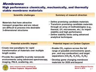
SMART MATERIALS- which adjust to the requirements "smart materials" also called intelligent materials or active materials describes a group of material systems with unique properties. The technological field of “smart materials” is not transparent or clearly structured. It has evolved over the past decades with increasing pace during the 1990s to become what it is today. • Smart materials, Intelligent Materials, Active Materials, Adaptive Materials and to some extent “actuators” and “sensors” are almost always used interchangeably. • Active materials - two groups. 1. The “classical” active materials as viewed by the academic community and is characterized by the type of response these materials generate. 2. Consists of materials that respond to stimuli with a change in a key material property, eg.electrical conductivity or viscosity • [Mention of medicines, packed items which will indicate the life with change in time, environment, decay etc; dress materials which will adjust with the human conditions etc. etc.]
Self diagnostic materials Optic fibres composite Smart composites Smart tagged composites • Temperature changing materials Thermoelectric materials • Thickness changing fluids Magneto-Rehological fluids (MRFs) • References Intelligent MaterialsSmart materials workshop
Smart Materials A smart material with variable viscosity may turn from a fluid which flows easily to a solid. A smart fluid developed in labs at the Michigan Institute of Technology
Smart Materials Also termed as Responsive Materials • "Smart" materials respond to environmental stimuli with particular changes in some variables. Also called responsive materials. Depending on changes in some external conditions, "smart" materials change either their properties (mechanical, electrical, appearance), their structure or composition, or their functions. Mostly, "smart" materials are embedded in systems whose inherent properties can be favorably changed to meet performance needs.
Self diagnostic materials Optic fibres composite Smart composites Smart tagged composites • Temperature changing materials Thermoelectric materials • Thickness changing fluids Magneto-Rehological fluids (MRFs) • References Intelligent MaterialsSmart materials workshop
Shape Memory Alloys (SMA) • Shape memory alloys (SMA's) are metals, which exhibit two very unique properties, pseudo-elasticity, and the shape memory effect. Arne Olander first observed these unusual properties in 1938 (Oksuta and Wayman 1938), but not until the 1960's were any serious research advances made in the field of shape memory alloys. The most effective and widely used alloys include NiTi (Nickel - Titanium), CuZnAl, and CuAlNi
Shape Memory Alloys (SMA) • Shape memory alloys (SMA's) are metals, which exhibit two very unique properties, pseudo-elasticity, and the shape memory effect. • The most effective and widely used alloys include NiTi (Nickel - Titanium), CuZnAl, and CuAlNi
Applications of Shape Memory Alloys • Aeronautical Applications: • Surgical Tools: • Muscle Wires
SHAPE MEMORY EFFECT Implemented in: • Coffee pots • The space shuttle • Thermostats • Vascular Stets • Hydraulic Fittings (for Airplanes)
SHAPE MEMORY EFFECT Implemented in: • Coffee pots • The space shuttle • Thermostats • Vascular Stets • Hydraulic Fittings (for Airplanes)
Microscopic and Macroscopic Views of the Two Phases of Shape Memory Alloys
How Shape Memory Alloys Work The Martensite and Austenite phases
Applications of Shape Memory Alloys • Aeronautical Applications: • Surgical Tools: • Muscle Wires
Pseudo-elasticity Applications in which pseudo-elasticity is used are: Eyeglass Frames Under garments Medical Tools Cellular Phone Antennae Orthodontic Arches Load Diagram of the pseudo-elastic effect Occurring
Advantages and Disadvantages of SMAs • Bio-compatibility • Diverse Fields of Application • Good Mechanical Properties (strong, corrosion resistant) Relatively expensive to manufacture and machine. Most SMA's have poor fatigue properties; this means that while under the same loading conditions (i.e. twisting, bending, compressing) a steel component may survive for more than one hundred times more cycles than an SMA element
Ferromagnetic Shape Memory Alloys (FSMA) – • Ferromagnetic Shape Memory Alloys (FSMA) Recently discovered class of actuator material, Magnetically driven actuation (field intensity varies, about 3KG and larger) and • large strains (around 6%). • FSMA are still in the development phase • Alloys in the Ni-Mn-Ga ternary. • FSMAs are ferromagnetic alloys which also support the shape memory effect.
OPTICAL FIBRE • Made of extremely pure silica. • Thinner than a human hair and stronger than a steel fibre of similar thickness. It can carry thousands of times more information than a copper wire! • Optical fibre cables have the advantage of being lighter and taking less space than copper wire cables for the same information capacity.
Fabrication of Optical Fibres • The best cakes are made of the best ingredients. • To make a good optical fibre, we need to start with good quality materials, that is highly purified materials. • The presence of impurities alter the optical properties of the fibre. • There are several ways to manufacture optical fibres: • Directly drawing the fibre from what is called a preform. • The fibre is then drawn from the preform • i) Direct Techniques • Two methods can be used to draw a fibre directly: • Double Crucible method • Rod in Tube method
1. Double Crucible The molten core glass is placed in the inner crucible. The molten cladding glass is placed in the outer crucible. The two glasses come together at the base of the outer cucible and a fibre is drawn. Long fibres can be produced (providing you don't let the content of the crucibles run dry!). Step-index fibres and graded-index fibrescan be drawn with this method.
2. Rod in Tube A rod of core glass is placed inside a tube of cladding glass. The end of this assembly is heated; both are softened and a fibre is drawn. Rod and tube are usually 1 m long. The core rod has typically a 30 mm diameter. The core glass and the cladding glass must have similar softening temperatures. This method is relatively easy: just need to purchase the rod and the tube. However, must be very careful not to introduce impurities between the core and the cladding.
ii) Deposition Techniques • Most optical fibres are made from preforms. The preforms are made by deposition of silica and various dopants from mixing certain chemicals; the fibre is then drawn from the preform. • Many techniques are used to make preforms. Among them: • · Modified Chemical Vapour Deposition or MCVD • · Plasma-Enhanced Modified Chemical Vapour Deposition or PMCVD • · Outside Vapour Deposition or OVD • · Axial Vapour Deposition or AVD
The Chemicals • Oxygen (O2) and silicon tetrachloride (SiCl4) react to make silica (SiO2). • Pure silica is doped with other chemicals such as boron oxide (B2O3), germanium dioxide (GeO2) and phosphorus pentoxide (P2O5) are used to change the refractive index of the glass.
The chemicals are mixed inside a glass tube that is rotating on a lathe. • They react and extremely fine particles of germano or phosphoro silicate glass are deposited on the inside of the tube. • A travelling burner moving along the tube: causes a reaction to take place and then fuses the deposited material. • The preform is deposited layer by layer starting first with the cladding layers and followed by the core layers. • Varying the mixture of chemicals changes the refractive index of the glass. • When the deposition is complete, the tube is collapsed at 2000 C into a preform of the purest silica with a core of different composition. • The preform is then put into a furnace for drawing.
Plasma-Enhanced Modified Chemical Vapour Deposition (PMCVD) Plasma-Enhanced Modified Chemical Vapour Deposition is similar in principle to MCVD. The difference lies in the use of a plasma instead of a torch. The plasma is a region of electrically heated ionised gases. It provides sufficient heat to increase the chemical reaction rates inside the tube and the deposition rate. This technique can be used to manufacture very long fibres (50 km).It is used for both step index and graded index fibres.
Outside Vapour Deposition (OVD) The chemical vapours are oxidised in a flame in a process called hydrolysis. The deposition is done on the outside of a silica rod as the torch moves laterally.When the deposition is complete, the rod is removed and the resulting tube is thermally collapsed
Axial Vapour Deposition (AVD) The deposition occurs on the end of a rotatingsilica boule as chemical vapors react to form silica. Core preforms and very long fibres can be made with this technique. Step-index fibres and graded-index fibres can be manufactured this w
From Preform to Fibre • All these deposition techniques produce preforms. These are typically 1 m long and have a 2 cm diameter but these dimensions vary with the manufacturer. • The preform is one step away from the thin optical fibre. This step involves a process called drawing.
Fibre Drawing and Spooling • During this last step of the fabrication process, many things will happen to the fibre: • · the fibre is drawn from the preform. • · it is quality checked • · it is coated for protection • · it is stored on a spool (just like a photographic film).
The tip of the preform is heated to about 2000°C in a furnace. As the glass softens, a thin strand of softened glass falls by gravity and cools down. • As the fibre is drawn its diameter is constantly monitored • A plastic coating is then applied to the fibre, before it touches any components. The coating protects the fibre from dust and moisture. • The fibre is then wrapped around a spool.
Fabrication of an Optical Fibre Heating the preform Drawing the fibre
Piezoelectric Materials 1. When a piezoelectric material is deformed, it gives off a small but measurable electrical discharge 2. When an electrical current is passed through a piezoelectric material it experiences a significant increase in size (up to a 4% change in volume) Most widely used as sensors in different environments To measure fluid compositions, fluid density, fluid viscosity, or the force of an impact Eg: Airbag sensor in modern cars- senses the force of an impact on the car and sends and electric charge deploying the airbag.
Electro-Rheostatic (ER) and Magneto-Rheostatic(MR) materials These materials are fluids, which can experience a dramatic change in their viscosity Can change from a thick fluid (similar to motor oil) to nearly a solid substance within the span of a millisecond when exposed to a magnetic or electric field; the effect can be completely reversed just as quickly when the field is removed.
THERMOPLASTICS • THERMOSETTING PLASTICS • ELASTOMERS printouts shall be supplied
ABOUT • METALLIC COATINGS • DIFFUSION COATINGS • ANODISING • POWDER COATING • THERMOPLASTICS • THERMOSETTING PLASTICS • ELASTOMERS printouts shall be supplied
Self diagnostic materials Optic fibres composite Smart composites Smart tagged composites • Temperature changing materials Thermoelectric materials • Thickness changing fluids Magneto-Rehological fluids (MRFs) • References Intelligent MaterialsSmart materials workshop
Ferromagnetic Shape Memory Alloys (FSMA) – • Ferromagnetic Shape Memory Alloys (FSMA) Recently discovered class of actuator material, Magnetically driven actuation (field intensity varies, about 3KG and larger) and • large strains (around 6%). • FSMA are still in the development phase • Alloys in the Ni-Mn-Ga ternary. • FSMAs are ferromagnetic alloys which also support the shape memory effect.
Advantages and Disadvantages of SMAs • Bio-compatibility • Diverse Fields of Application • Good Mechanical Properties (strong, corrosion resistant) Relatively expensive to manufacture and machine. Most SMA's have poor fatigue properties; this means that while under the same loading conditions (i.e. twisting, bending, compressing) a steel component may survive for more than one hundred times more cycles than an SMA element
THERMOPLASTICS • THERMOSETTING PLASTICS • ELASTOMERS printouts shall be supplied
CAST IRON • GRAY C.I. • DUCTILE C.I • WHITE C.I. • MALLEABLE IRON • COMPACTED GRAPHITE IRON • Also by stress levels as: • ferritic, Pearlitic, Quenched and tempered, Austempered
Unit Operations in Polymer Processing Thermoplastic and thermoset melt processes may be broken down into: • Preshaping • Shaping • Shape Stabilization Chee 390
Unit Operations in Polymer Processing • Preshaping steps: • Solids handling and conveying: most processes usually involve feed in particulate form • Plastication: The creation of a polymer melt from a solid feed. • Mixing: often required to achieve uniform melt temperature or uniform composition in compounds • Pumping : The plasticated melt must be pressurized and pumped to a shaping device • Shaping: The polymer melt is forced through the shaping devices to create the desired shape. • The flow behavior (rheology) of polymer melts influences the design of the various shaping devices, the processing conditions and the rate at which the product can be shaped. • Shape stabilization: • Involves the solidification of the polymer melt in the desired shape, through heat transfer Chee 390
The Single Screw Plasticating Extruder • Regions 1, 2, 3: Handling of particulate solids • Region 3: Melting, pumping and mixing • Region 4: Pumping and mixing • Regions 3+4: Devolatilization (if needed) Chee 390
Product Shaping / Secondary Operations EXTRUSION Final Product (pipe, profile) • Secondary operation • Fiber spinning (fibers) • Cast film (overhead transparencies, • Blown film (grocery bags) Shaping through die • Preform for other molding processes • Blow molding (bottles), • Thermoforming (appliance liners) • Compression molding (seals) Chee 390
Annular (Tubular) Dies In a tubular die the polymer melt exits through an annulus. These dies are used to extrude plastic pipes. The melt flows through the annular gap and solidifies at the exit in a cold water bath. Chee 390
Profile dies Profiles are all extruded articles having cross-sectional shape that differs from that of a circle, an annulus, or a very wide and thin rectangle (such as flat film or sheet) To produce profiles for windows, doors etc. we need appropriate shaped profile dies. The cross-section of a profile die may be very complicated Chee 390