Download
1 / 41
420 likes | 912 Vues
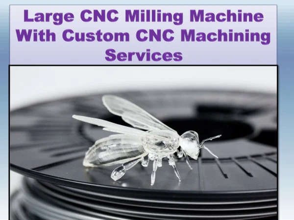
WFT 13 CNC Horizontal Milling Machine. Presentation machine WFT 13 CNC. WFT 13 CNC Horizontal Milling Machine. Manufacturer: CTPark Brno Tuřanka 104 627 00 Brno - Slatina. WFT 13 CNC Horizontal Milling Machine. Basic concepts. Linear guiding. Electro-optic linear.

E N D
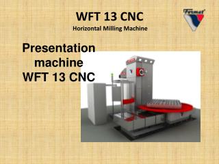
WFT 13 CNC Horizontal Milling Machine Presentation machine WFT 13 CNC
WFT 13 CNC Horizontal Milling Machine Manufacturer: CTPark Brno Tuřanka 104 627 00 Brno - Slatina
WFT 13 CNC Horizontal Milling Machine Basic concepts Linear guiding Electro-optic linear
WFT 13 CNC Horizontal Milling Machine Basic concepts Ball screw
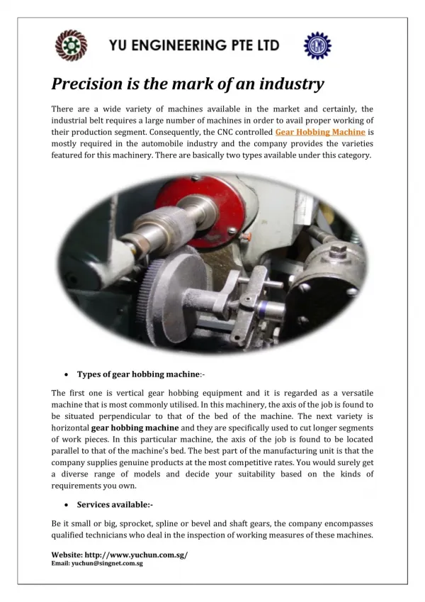
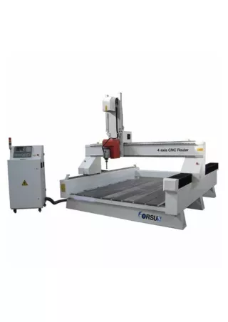
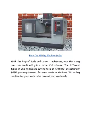
WFT 13 CNC Horizontal Milling Machine Basic characteristics of the machine The WFT 13 CNC is a new machine of its modern design. It is designed with standardized components of world renowned manufacturers mostly (Bosch, Siemens, Heidenhain, SKF,…). Thanks to such design, a high variability has reached together with a favourable rate price/output and with the advantageous worldwide service assistance. The Horizontal Milling and Boring Machine WFT 13 CNC is a continuously controlled table-type milling and boring machine of its up-to-date design, which is ideal for a powerful complete machining of work pieces up to 15 tons.
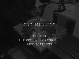
WFT 13 CNC Horizontal Milling Machine Basic characteristics of the machine • continuously controlled Horizontal Milling and Boring Machine WFT 13 CNC • T arrangement of beds • 4 linear axes + rotary table • out-travel working spindle • the machine is designed for its universal employment in the engineering production • it is suitable as for rough operations, as for a precise machining of moulds • optionally, it can be equipped with a tool magazine with manipulator (ATC), cooling of tools through the spindle axis, conveyer of chips
WFT 13 CNC Horizontal Milling Machine Basic characteristics of the machine The machine is equipped with the CNC control system HEIDENHAIN iTNC 530 (SIEMENS Sinumeric 840D), which enables control of four axes X, Y, Z, W in the positional confinement (the spindle out-travel axis as an auxiliary one) and axis C in the speed confinement. The positional measurement at the coordinates X, Y, Z and W is carried out by an encoder (optionally by linear measurement of X,Y,Z). The spindle angle positioning in the axis C is controlled by a rotary sensor and the mutual positional coupling of the spindle and the feeding screw enables cutting of threads.
B H C D E G F H WFT 13 CNC Horizontal Milling Machine To make understanding of the machine separate functions easy and to help your orientation in the Instruction Manual itself, we have parted the machine to following groups: • Headstock • Frame • Headstock slide • Frame slide • Crosswise bed (axis Z) • Rotary table • Slide of the rotary table • Longitudinal bed (axis X) A
WFT 13 CNC Horizontal Milling Machine Headstock The headstock is a cast part of nodular cast iron, in which the working spindle and two-stage gear-box are assembled. Gears are shifted automatically acc. to the preset speed of the spindle. For the drive the spindle asynchronous motor is applied, enabling steeples speed regulation. The headstock is designed for machine tools, where material is cut by turning tools (milling cutter, drill,…), clamped in the rotating spindle, or in special technological accessories approved by the machine manufacturer.
WFT 13 CNC Horizontal Milling Machine Headstock The headstock can be used for drilling, boring, milling, thread cutting and grinding. It is designed namely for its assembly on horizontal boring and milling machines. These machine tools serve for machining of case, or plate shaped work pieces, as well as for complicated parts of grey and nodular cast iron, cast steel, steel and non-ferrous materials.
WFT 13 CNC Horizontal Milling Machine The headstock consists of following main parts: • Slide: • Spindle drive: • Main seating: • Out-travel drive: • Working spindle: • Hollow spindle:
WFT 13 CNC Horizontal Milling Machine Headstock scheme Drive of spindle out-travel Ball screw Main motor Gear-box ZF Belt transmission Inlet of cooling Working spindle Hollow spindle House of out-travel house Clamp Slide Main seating
WFT 13 CNC Horizontal Milling Machine Headstock slide This is the cast. Sleigh provides vertical movement in the Y, Z using linear lines, which is located on the stand. While ensuring the movement of the strip axis using linear lines, which is located on the strip. Headstock Headstock slide
WFT 13 CNC Horizontal Milling Machine Stiffening flange It serves for the out-travelled spindle stiffening, by which a higher rigidity and steadiness at machining can be reached. Inlet of cooling Slide Stiffening flange Working spindle
WFT 13 CNC Horizontal Milling Machine Frame The frame is a column-type casting of steel cast GG 30+0,2 Cr+0,6 Cu. It is richly ribbed. By the lower flange it is screwed to the frame slide. The frame comprises a feeding mechanism with a motion screw for the headstock travel. One end of the feeding screw is assembled in the console body with the motor on the frame upper flange and the other end id seated in the bearing body on the frame slide.
WFT 13 CNC Horizontal Milling Machine Frame • The measurement of the Y-axis is carried out by means of scanning from the motor by means of the “Encoder “ (optionally a linear optic measurement by a ruler is available). • The ball screw nut, all sliding surface for the headstock travel are lubricated centrally by an oil lubrication system. The ZARN bearing of the ball screw is greased by a grease filling acc. to the lubrication plan of this Instruction manual.
WFT 13 CNC Horizontal Milling Machine Frame of the machine
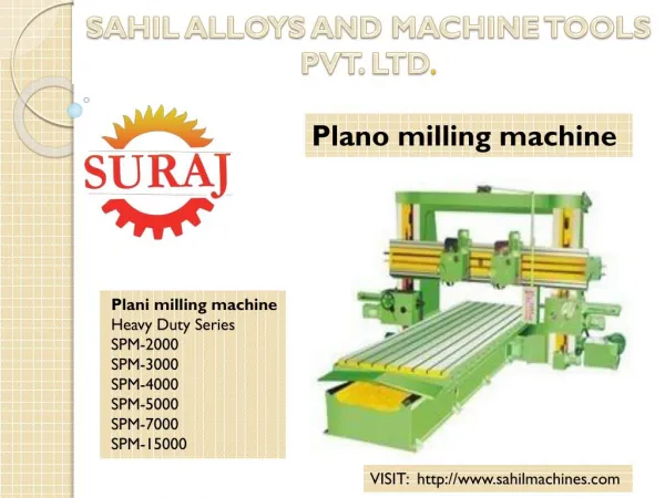
WFT 13 CNC Horizontal Milling Machine Longitudinal bed (axis X) The group table and table slide creates one assembly unit. These parts arecastings of grey iron GG 30. From below the table slide is guided along the crosswise bed by a sliding way. This machine is equipped with the rotary table of our own design and production. The rotary table with its longitudinal adjustment consists of the firm bed, on which the table slide with the rotationally seated table is moving. The table positional measurement in the axis B is performed by an angle sensor, which is fixed to the firm pin in the table centre.
WFT 13 CNC Horizontal Milling Machine Longitudinal bed (axis X)
WFT 13 CNC Horizontal Milling Machine Platform for operators (Screen) The platform for operators is fastened to the foundation. Inside the cabinet the main control panel of the control system is installed and there are also storage compartments for tools prepared here. By large loopholes a sufficient lookout is guaranteed. Safety elements on the cabinet door and a hardened safety glass provide the safety of operators.
WFT 13 CNC Horizontal Milling Machine Screen(operators cabinet) with the control panel
WFT 13 CNC Horizontal Milling Machine Control system – Heidenhain, iTNC 530 The machine is equipped with the CNC control system HEIDENHAIN iTNC 530 (SIEMENS Sinumeric 840D), which enables control of four axes X, Y, Z, W in the positional confinement (the spindle out-travel axis as an auxiliary one) and axis C in the speed confinement. The positional measurement at the coordinates X, Y, Z and W is carried out by an encoder (optionally by linear measurement of X,Y,Z).
WFT 13 CNC Horizontal Milling Machine Main control panel and hand controllers HR 420 HR 410
WFT 13 CNC Horizontal Milling Machine Conveyer of chips For obtaining chips from the work area can use the machine screw or belt conveyors chips. The conveyer of chips serves, at the same time, as a cooling liquid downlead and the first stage of its filtration. By this conveyer rough impurities are transported into the vessel, prepared at the conveyer outlet.
WFT 13 CNC Horizontal Milling Machine Conveyer of chips
WFT 13 CNC Horizontal Milling Machine Outer rinsing cooling • The outer rinsing cooling creates an integral part of the machine WFT 13, until otherwise required by the customer. • From the conveyer of chips cooling emulsion is pumped-over to the main sludge reservoir of its 550 l capacity. From this reservoir emulsion is pumped by a pump of its outlet 55 l/min and displacement 4 bars through the headstock up to the tool by hoses.
WFT 13 CNC Horizontal Milling Machine Pump and sludge reservoir of the rinsing cooling
WFT 13 CNC Horizontal Milling Machine Hydraulic aggregate – HYTEK • The hydraulic aggregate serves for the tool unclamping (8 - 10 MPa). Furthermore, it serves also for the rotary table stiffening (axis B), where pressure is decreased by a reduction valve to 0,6 MPa.
WFT 13 CNC Horizontal Milling Machine Hydraulic aggregate – HYTEK
WFT 13 CNC Horizontal Milling Machine Other clamping elements Clamping block Clamping angle
WFT 13 CNC Horizontal Milling Machine Table • This machine is equipped with the rotary table of our own design and production. The rotary table with its longitudinal adjustment consists of the firm bed, on which the table slide with the rotationally seated table is moving. The table positional measurement in the axis B is performed by an angle sensor, which is fixed to the firm pin in the table centre. The machine is currently equipped with one motor Harmonic Drive and two mechanically pre-tensioned pinions for the play elimination in the toothed rim (optionally, the machine can be delivered with its two-motors version and the play is then eliminated by the electronic system MASTER – SLAVE).
WFT 13 CNC Horizontal Milling Machine Table • Travel in the axis X is delivered in standard lengths 1500, 2000, 2500, 3000, 3500, 4000 mm. Following rotary table sizes can be delivered: • Rotary table 1 600 x 1 800 mm • Rotary table 1 800 x 2 200 mm
WFT 13 CNC Horizontal Milling Machine Manual universal milling head UHM 30 • It is a universal manual milling head, serving for machining of upper, side and oblique surfaces. • If a linear interpolation is used, also drilling and boring of oblique holes is available by means of this milling head.
WFT 13 CNC Horizontal Milling Machine Basic technical data • Clamping taper ISO 50 • (or BT 50) • Tool DIN 69871 – clamping stem DIN 69872 ISO 7388, type A • (or MAS P50T-1 (45°)) • Hydraulic releasing of tools • Axial compensator on the main headstock; on the released tool • Maximal speed: • 3000 r.p.m. – with the standard version • Maximal output: 26 kW • Milling head turning 180° • Maximal torque 1600 Nm
WFT 13 CNC Horizontal Milling Machine Basic machine motions WFT 13 CNC Description of the separate machine motion axes: X – Longitudinal motion of the table Y – Vertical motion of the headstock Z – Crosswise motion of the frame W – Out-travel of the working spindle B – Rotation of the table C – Rotation of the working spindle
WFT 13 CNC Horizontal Milling Machine Basic technical data of the machine
WFT 13 CNC Horizontal Milling Machine Basic technical data of the machine
WFT 13 CNC Horizontal Milling Machine Basic technical data of the machine
WFT 13 CNC Horizontal Milling Machine Basic technical data of the machine
WFT 13 CNC Horizontal Milling Machine Thank you for your attention JH