Download

1 / 36
420 likes | 1.56k Vues
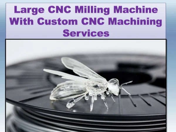
This comprehensive guide explores the fundamentals of CNC (Computer Numerical Control) milling, highlighting the differences between conventional and CNC machining, as well as the distinctions between lathe and milling processes. It delves into the parts of CNC machines, the programming unit, and the control mechanisms involved. With a focus on improving productivity and achieving high-quality outputs at minimal costs, this document serves as an essential resource for understanding modern milling technologies, their operation, and programming using Heidenhain ISO standards.

E N D
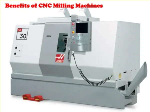
Welcome to CNC MILLING Heidenhain ISO
Introduction Difference Between Conventional & CNC M/cing
INTRODUCTION • FUNDAMENTAL PRINCIPLES • INSTRUCTION
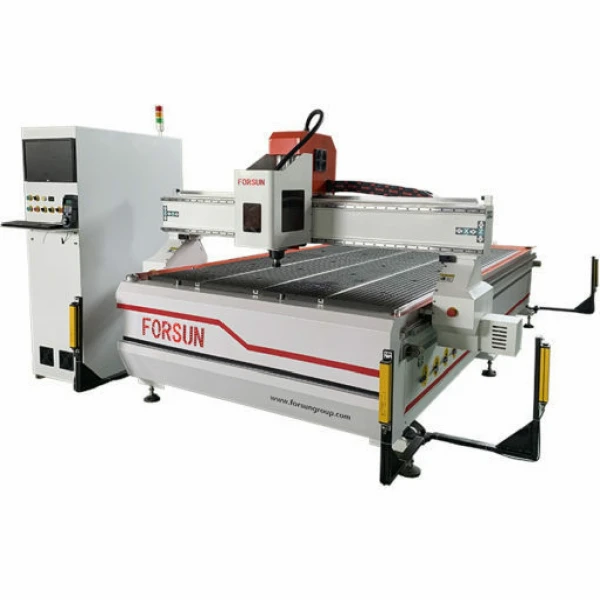
1. INTRODUCTION • Ways of Machining • Parts of CNC Machine • Working Methods of CNC
Ways of Machining • Conventional or Traditional • Numerical Control (NC) • Computer Numerical Control (CNC)
Difficulties with Conventional System • Complex shapes are difficult to machine • Depends on the human skill • Frequent & repeated measurements are required • Difficult to achieve consistency in product quality • High Changeover Time • Less productive hours • More scrap is generated
Current Market Demand • High quality products at Lowest cost in Minimum time with wide range of variety Answer to the above is NC System
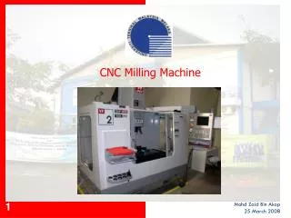
Parts of NC/CNC Machine • Programming Unit • Machine Control Unit • Machine Tool Unit CNC NC
Programming Unit • Programmer • Computer system • User Interface device • Data Storage and Transfer facility
Machine Control Unit • Tape Reader • Data Buffer • Signal Output Channels to Machine Tool • Feedback channels from the Machine Tool
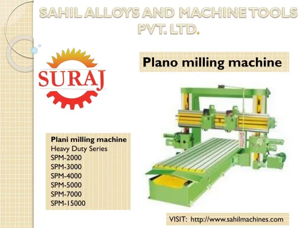
Machine Tool • Structure • Extra Rigid • Easy chip disposal System, eg: Use of Slant Bed • Thermal Resistant • Drives • AC Induction motors • DC motors
Machine Tool • Actuation System • Stepper motor/servomotor • Ball Screw & nut with support bearing • Feed back devices on closed loop system • Linear Bearing • Tool & Work handling Devices • Automatic Tool Changers (ATCs) • Turret Head • Automatic Pallet Changers • Hydraulic/Pneumatic Tool/Work Clamping System
2. Fundamental Principles • Coordinate System • Longitudinal Motion • Transverse Motion • Dimensioning System • Absolute • Incremental • Mixed • Reference System • Machine Reference • Work Reference
Instruction or program • Introduction N 10 G 00 X 50.0 Z 25.0 ; Block Words End of Block Block No. G 00 Data Address
Basic Program Structure • Working unit • Mm: G71 • Inch: G70 • Working Plane • XY: G17 • ZX: G18 • YZ: G19 • Dimensioning method • Absolute: G90 • Incremental: G91
Simple Example Program (Absolute) % 101 G71 N05 G90 G17 N10 G30 X0 Y0 Z-10 N20 G31 X100 Y100 Z0 N30 G99 T1 L0 R5 N40 M06 T1 N50 M03 S2000 N60 G90 G00 X20 Y20 N62 G01 Z5 F250 N65 G01 Z0 F100 N70 G01 Z-1 F50 N80 G01 X80 Y20F100 N90 Y80 X80 N100 X20 N110 Y20 N120 G00 Z5 N130 M05 N140 M30 N150 % 101 G71
Simple Example Program (Incremental) % 102 G71 N05 G90 G17 N10 G30 X-50 Y-50 Z-10 N20 G31 X50 Y50 Z0 N30 G99 T1 L0 R3 N40 M06 T1 N50 M03 S2000 N60 G90 G00 X-40 Y0 Z10 N65 G01 Z0 F500 N70 G01 Z-1 F50 N80 G91 Y-40 N90 X80 N100 Y80 N110 X-80 N120 Y-40 N130 G00 Z10 N140 M05 N150 M30 N160 % 102 G71
Example Program • Use of G02/G03 • Use of G40/G41/G42 • Use of Tangential Approach % 103 G71 N10 G90 G17 N20 G30 X-30 Y-30 Z-20 N30 G31 X30 Y30 Z0 N40 G99 T1 L0 R7 N50 M06 T1 N60 M03 S2000 N70 G90 G00 Z50 N80 G00 X0 Y-55 N90 G01 Z1 F500 N95 Z0 F50 N100 G41 Z-5 F50 N110 G03 X0 Y-25 R15 F300 N120 G01 X-20 Y-25
Contd… N130 G02 X-25 Y-20 R5 N140 G01 X-25 Y20 N150 G02 X-20 Y25 R5 N160 G01 X20 Y25 N170 G02 X25 Y20 R5 N180 G01 X25 Y-20 N190 G01 X20 Y-25 N200 G01 X0 Y-25 N210 G03 X0 Y-55 R15 N220 G00 G40 Z50 N230 M05 N240 M30 N250 % 103 G71
Depth of Cut Increment Method %1002 G71 N100 G17 G90 N200 G30 X-45 Y-45 Z-15 N300 G31 X+45 Y+45 Z+0 N400 G99 T1 L+0 R+7 N500 G00 G40 G90 N600 T1 M06 N700 S1000 M03 N800 G00 X-55 Y+0 Z+10 N900 Z+0 N1000 G98 L1 N1100 G01 G41 G91 Z-1 F100 N1200 G90 X-30 Y+0 F80 N1300 X-30 Y+20
N1400 X-20 Y+30 N1410 X20 Y30 N1500 G02 X+30 Y+20 R+10 N1600 G01 X30 Y-20 N1700 G02 X+20 Y-30 R+10 N1800 G01 X-20 Y-30 N1850 X-30 Y-20 N1860 X-30 Y0 N1870 G0 G40 X-55 Y0 N1900 L1.4 N2000 G98 L0 N2100 G40 Z+20 N2200 M30 N9999 %1002 G71
Linear & circular polar Method %1003 G71 N20 G17 N40 G17 G30 G90 X+0 Y+0 Z-10 N60 G31 G90 X+100 Y+100 Z+0 N80 G99 T1 L+0 R+3 N90 T1 N110 G01 M06 N120 S2000 N140 G01 M03 N180 G00 G90 X+20 Y+20 Z+5
N200 G01 G90 Z-1 F50 N220 G90 I+20 J+20 G29 N240 G11 G90 R+80 H+45 F100 N260 G90 I+50 J+50 G29 N280 G12 G90 H-55 N300 G07 G90 X+20 F60 N320 G00 G90 Z+5 N340 G01 M30 N9999 %1003 G71
Peck Drilling Cycle (G83) Writing Format: G83 P01…. P02…. P03…. P04…. P05…. Where; P01: Setup Clearance P02: Total Depth P03: Pecking Depth P04: Dwell Time (in Seconds) P05: Feed Rate P01 P03 P02 P03
Program for Array Drilling %1005 G71 N05 G17 G90 N10 G30 X-45 Y-45 Z-15 N20 G31 X+45 Y+45 Z0 N30 G99 T1 L+0 R+4 N31M06 T1 N32 M03 S2000 N40 G90 G40 G00 X-40 Y-30 N45 G01 Z10 F800 N50 G01 Z3 F100 N60 G83 P01 -1 P02 -5 P03 -1P04 0.1P05 100 N65 Z1 M99 N70 G98 L1 N80 G17 X-40 Y30 G90 N90 G00 Z1 M99 N100 G98 L2 N110 G17 G91 G01 X10 F100 N120 G90 G00 Z1 M99 N130 L2.5
Contd.. N140 G98 L3 N150 G17 G91 Y-15 N133 G00 G90 Z+1 M99 N134 L3.2 N135 G98 L4 N136 G17 G91 X-15 N137 G00 G90 Z+1 M99 N134 L4.2 N140 G00 Z1 M99 N142 G00 Z10 N144 G98 L0 N145 M05 N150 M30 N9999 %1005 G71 10 10 15 15 15 15
Rectangular Pocket Milling Writing Format G75 P01… P02 … P03 … P04 … P05 … P06 … P07 … P01: Setup Clearance P02: Total Depth P03: Pecking Depth P04: Feed Rate in Z-axis P05: 1st Side Length of Pocket P06: 2nd Side Length of Pocket P07: Feed Rate for Cutting G75 : Rectangular Pocket Milling Clockwise G76: Rectangular Pocket Milling Anti Clockwise
SAMPLE PROGRAM %1007 G71 N05 G17 G90 N10 G30 X-45 Y-45 Z-15 N20 G31 X+45 Y+45 Z0 N30 G99 T1 L+0 R+7 N40 G40 G90 N45 M06 T1 N50 M03 S1500 N60 G00 X0 Y0 Z10 N61 G00 Z5 N70 G75 P01 -3 P02 -5 P03 -1 P04 50 P05 X+40 P06 Y+30 P07 100 N80 G00 Z3 M99 N90 G00 Z10 N100 M30 N9999 %1007 G71
SLOT Milling Writing Format G74 P01… P02 … P03 … P04 … P05 … P06 … P07 … P01: Setup Clearance P02: Total Depth P03: Pecking Depth P04: Feed Rate in Z-axis P05: 1st Side Length of Slot P06: 2nd Side Length of Slot P07: Feed Rate for Cutting
SAMPLE PROGRAM %1008 G71 N05 G17 G90 N10 G30 X0 Y0 Z-15 N20 G31 X+90 Y+90 Z0 N30 G99 T1 L+0 R+3 N40 G40 G90 N50 M03 S1500 N60 G00 X20 Y20 N65 G01 Z10 F250 N68 G00 Z3 N70 G74 P01 -3 P02 -5 P03 -1 P04 50 P05 X+40 P06 Y+10 P07 100 N90 G00 Z3 M99 N100 G90 I20 J20 G10 R60 H90 M99 N110 G00 Z10 N120 M05 N120 M30 N9999 %1008 G71 40 10 R60,<90 10 20 R 20
MIRRORING Writing Format G28 X Where, X is the name of axis in which mirroring will take place %1010 G71 N05 G17 G90 N10 G17 G30 X-50 Y-50 Z-10 N20 G31 X+50 Y+50 Z+0 N30 G99 T1 L+0 R+3 N40 T1 M06 N40 G40 G90 N50 S1500 M03 N60 G90 X+0 Y+0 Z+5 N70 G98 L150 N80 G00 X+10 Y+10 N82 G01 Z+5 F500 N85 G01 Z0 F100 N90 G01 Z-1 F50
N100 G01 X+20 Y+10 F100 N110 G01 X+20 Y+15 N112 X15 Y15 N114 Y25 N116 X30 N118 Y30 N120 X10 N122 Y10 N124 G00 Z+5 N140 G98 L0 N150 G28 X L150 N160 G28 X Y L150 N170 G28 Y L150 N180 G00 Z+5 N200 M05 G00 Z20 N100 M30 Y x