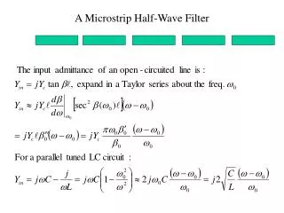
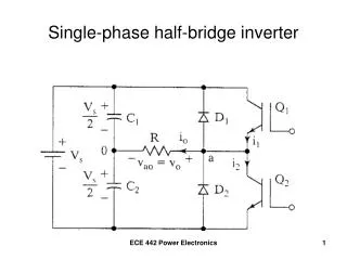
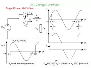
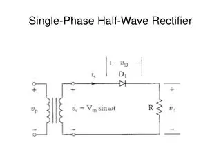
Single-Phase Half-Wave Rectifier
Single-Phase Half-Wave Rectifier. Waveforms. Single-Phase Half-Wave Rectifier. Performance Parameters. Average value of the output voltage, V dc Average value of the output current, I dc Output dc power, P dc P dc = V dc I dc rms value of the output voltage, V rms Output ac power, P ac

Single-Phase Half-Wave Rectifier
E N D
Presentation Transcript
Performance Parameters • Average value of the output voltage, Vdc • Average value of the output current, Idc • Output dc power, Pdc • Pdc = VdcIdc • rms value of the output voltage, Vrms • Output ac power, Pac • Pac = VrmsIrms
Performance Parameters (continued) • Efficiency, η • η = Pdc/Pac • Effective (rms) value of the ac component of the output voltage, Vac • Vac = Vrms2 – Vdc2 • Form factor, FF • FF = Vrms/Vdc • Ripple factor, RF • RF = Vac/Vdc
Performance Parameters (continued) • Alternate form for ripple factor • Transformer utilization factor, TUF • TUF = Pdc/VsIs • Vs, Is are rms voltage and current of the transformer secondary
Performance Parameters (continued) • Displacement angle, Φ • Displacement Factor, DF • DF = cos(Φ) • Harmonic Factor, HF
Performance Parameters (continued) • Power Factor, PF
Performance Parameters (continued) • Crest Factor, CF
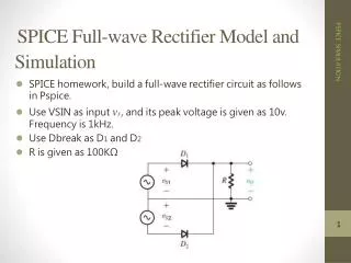
Example 3.1 • Determine η, FF, RF, TUF, PIV of the diode, CF of the input current, input PF.
Determine the PIV • PIV is the maximum (peak) voltage that appears across the diode when reverse biased. Here, PIV = Vm. - - + PIV +
Summary – Half-Wave Rectifier • RF=121% High • Efficiency = 40.5 Low • TUF = 0.286 Low • 1/TUF = 3.496 • transformer must be 3.496 times larger than when using a pure ac voltage source
Waveforms of Current and Voltage Conduction period of D1 extends beyond ωt = π
Average Output Voltage Increase average voltage and current by making σ = 0
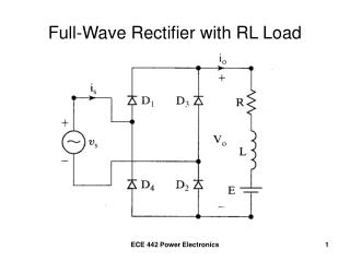
Application as a Battery Charger Diode conducts for vs > E, starting when Vmsinα = E
Waveforms for the Battery Charger Diode turns off when vs < E (at β = π – α) Charging current io = (vs – E)/R io = (Vmsinωt – E)/R for α < ωt < β
Single-Phase Full-Wave Rectifier Center-Tapped Transformer
Single-Phase Full-Wave Rectifier PIV = 2Vm
Full-Wave Bridge with Waveforms Conduction pattern D1 – D2 D3 – D4 PIV = Vm