Six Sigma Quality Engineering
Six Sigma Quality Engineering. Week 7 Analyze Phase. Chapter 6 Outline. Process Map Inputs characteristics Cause & Effect Fishbone Diagram (Minitab) C&E Matrix (Excel) Failure Mode & Effect Analysis (FMEA) Process Capablity Cpk Cp Minitab Tutorial

Six Sigma Quality Engineering
E N D
Presentation Transcript
Six Sigma Quality Engineering Week 7 Analyze Phase
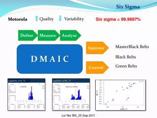
Chapter 6 Outline • Process Map • Inputs characteristics • Cause & Effect • Fishbone Diagram (Minitab) • C&E Matrix (Excel) • Failure Mode & Effect Analysis (FMEA) • Process Capablity • Cpk • Cp • Minitab Tutorial • In this session you will learn how to: · Produce X and R charts · Produce histograms with normal curves · Perform a process capability analysis
Characterising Inputs • Inputs can be classified as one of three types • Controllable (C) • Things you can adjust or control during the process • Speeds, feeds, temperatures, pressures…. • Standard Operating Procedures (S) • Things you always do (in procedures or common sense things) • Cleaning, safety…. • Noise (N) • Things you cannot control or don not want to control(too expensive or difficult) • Ambient temperature, humidity, operator...
Machining a shaft on a lathe Example Outputs (Y’s) Diameter Taper Surface finish C C C C C C C S C N N N S Inputs (x’s) Rotation speed Traverse speed Tool type Tool sharpness Shaft material Shaft length Material removal per cut Part cleanliness Coolant flow Operator Material variation Ambient temperature Coolant age
The Eight Steps in Cause and Effect Analysis • Define the Effect • Identify the Major Categories • Generate Ideas • Evaluate Ideas • Vote for the Most Likely Causes • Rank the Causes • Verify the Results • Recommend Solutions
Cause & Effect (Fishbone Diagram) • Objectives • To understand the benefits of Cause & Effect Analysis • To understand how to construct a C & E Diagram • Analysis • A method a work group can use to identify the possible causes of a problem • A tool to identify the factors that contribute to a quality characteristic
Uses of C & E (Fishbone Diagram) • Visual means for tracing a problem to its causes • Identifies all the possible causes of a problem and how they relate before deciding which ones to investigate • C & E analysis is used as a starting point for investigating a problem
C&E (Fishbone Diagram) • Effect • The problem or quality characteristic • The effect is the outcome of the factors that affect it Effect
Causes (Fishbone Diagram) • All the factors that could affect the problem or the quality characteristic • Five Major Categories • Materials • Methods • People • Machines • Environment
Machine Environment Effect Material Methods People
Cause and Effect (Matrix) • Benefit • Gain new knowledge and perspectives by sharing ideas with others • Helps us understand our processes • Provides a basis for action • Whenever a problem is discovered, using C&E analysis forces us to take a proactive stance by seeking out causes
2 1 5&6 3 4
C&E Matrix • Instructions This table provides the initial input to the FMEA and experimentation. When each of the output variables (requirements) are not correct, that represents potential "EFFECTS". When each input variable is not correct, that represents "Failure Modes". 1. List the process output variables 2. Rate each output on a 1-to-10 scale to importance to the customer 3. List process input variables (from the process map) 4. Rate each input's relationship to each output variable using a 0, 1, 3, 9 scale 5. Select the high ranking input variables to start the FMEA process; Determine how each selected input variable can "go wrong" and place that in the Failure Mode column of the FMEA.
FMEA • It is an approach to: • Identify potential failure for a product or a process • Estimate risks that are associated with causes • Determine actions to reduce risks • Evaluate product design validation plan • Evaluate process current control plan
FMEA types • There are two types: • Process: Will focus on Process Inputs • Design: Will used to analyze product designs before they are released to production
The use of the FMEA • Improve processes before failure occur (Proactive approach) • Prioritize resources to ensure process improvement efforts are beneficial to customers • Track and document completion of projects • It is a living document. It will be updated and reviewed all the time
Inputs & Outputs to FMEA Inputs • Process Map • C&E Matrix • Process History • Process technical procedures Outputs • Actions list to prevent causes • Actions list to detect failure modes • Document history of actions taken
FMEA step-by-step • For each process input, determine the ways in which the input can go wrong- the failure modes. What can go wrong with input
FMEA step-by-step • For each failure mode associated with the inputs, determine the effects of the failures on the customer. What the effect on outputs?
FMEA step-by-step • Identify potential causes of each failure mode. What are The causes?
FMEA step-by-step • List the current controls for each cause or failure mode (Prevent/Detect). How are these Found or prevented?
FMEA step-by-step • Create Severity, Occurrence, and Detection rating scales. • Severity of effect- importance of effect on customer requirements. It is a safety and other risks if failure occurs. • 1= Not Severe, 10= Very Severe • Occurrence of cause- frequency in which a give Cause occurs and creates Failure Mode. Can sometimes refer to the frequency of a failure mode. • 1= Not Likely, 10= Very Likely
FMEA step-by-step • Create severity, Occurrence, and Detection rating scales. • Detection- ability to: • Prevent the causes or failure mode from occurring or reduce their rate of occurrence • Detect the cause and lead to corrective action • Detect the failure mode • 1= Likely to Detect, 10= Not Likely at all to Detect
FMEA step-by-step • Risk Priority Number: • After rating we get the output on an FMEA Risk Priority Number. It is calculated as the product of Effects, Causes, and Controls RPN= Severity X Occurrence X Detection Effects Causes Controls
FMEA step-by-step • Dynamics of the Risk Priority Number: • The team defines the rating scales 1-10 for the severity, Occurrence, and Detection ratings. The team choose the levels and numbers: • How severe is it: Not Severe = 1 Somewhat = 3 Moderately = 5 Very Severe = 10
FMEA step-by-step • Dynamics of the Risk Priority Number: • The team defines the rating scales 1-10 for the severity, Occurrence, and Detection ratings. The team choose the levels and numbers: • How often does it Occur? Never/rarely = 1 Sometimes = 3 Half the time = 5 Always = 10
FMEA step-by-step • Dynamics of the Risk Priority Number: • The team defines the rating scales 1-10 for the severity, Occurrence, and Detection ratings. The team choose the levels and numbers: • How well can you detect it? Always = 1 Sometimes = 3 Half the time = 5 Never = 10
FMEA step-by-step • Determine recommended actions to reduce high RPN’s: What can be done?
FMEA step-by-step • Take appropriate actions and recalculate RPN’s Assign responsible Parties
Cpk & Cp • Cpk incorporates information about both the process spread and the process mean, so it is a measure of how the process is actually performing. • Cp relates how the process is performing to how it should be performing. Cp does not consider the location of the process mean, so it tells you what capability your process could achieve if centered.
Non-normal distributions • Use Capability Analysis (Nonnormal) to assess the capability of an in-control process when the data are from the nonnormal distribution. A capable process is able to produce products or services that meet specifications. • The process must be in control and follows a nonnormal distribution before you assess capability. If the process is not in control, then the capability estimates will be incorrect. • Nonnormal capability analysis consists of a capability histogram and a table of process capability statistics