Download
1 / 27
280 likes | 583 Vues
Status of ITER Project and Issues of Plasma-Wall Interaction. Michiya Shimada With contribution from Richard Pitts and David Campbell ITER Organization Seminar in ASIPP, Hefei 11 Dec. 2009. Contents. Status of ITER ITER’s objectives ITER design goals Main parameters of ITER

E N D
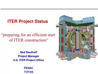
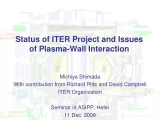
Status of ITER Project and Issues of Plasma-Wall Interaction Michiya Shimada With contribution from Richard Pitts and David Campbell ITER Organization Seminar in ASIPP, Hefei 11 Dec. 2009
Contents • Status of ITER • ITER’s objectives • ITER design goals • Main parameters of ITER • ITER construction site • ITER schedule • Design Review • PWI issues • Choice of Plasma-Facing Materials • Wall conditioning
ITER’s objectives • The overall programmatic objective: • to demonstrate the scientific and technological feasibility of fusion energy for peaceful purposes • The principal goal: • to design, construct and operate a tokamak experiment at a scale which satisfies this objective • ITER is designed to confine a DT plasma in which -particle heating dominates all other forms of plasma heating: • a burning plasma experiment
Physics: ITER is designed to produce a plasma dominated by a-particle heating produce a significant fusion power amplification factor (Q ≥ 10) in long-pulse operation aim to achieve steady-state operation of a tokamak (Q = 5) retain the possibility of exploring ‘controlled ignition’ (Q ≥ 30) Technology: demonstrate integrated operation of technologies for a fusion power plant test components required for a fusion power plant test concepts for a tritium breeding module ITER Design Goals
The main parameters of ITER are chosen to fulfill ITER’s goals
Updated Schedule (IO Proposal)
Design Review • During the Design Review that was conducted during the period 2006-2008, the recommendations were made in the following physics area: • Expansion and revision of the heat loads specifications associated with unmitigated disruptions, VDEs and ELMs have confirmed their serious consequences; implementation of their mitigation measures have been recommended • Improvement of the plasma shaping and position control capability • The divertor target material • TF ripple • Design changes and/or R&D programmes have been implemented in response to each of these recommendations. In some cases further analysis and experimental work is required, either to complete design specifications (e.g. in-vessel coils) or to provide an improved physics basis for the operation of ITER (e.g. the use of a full tungsten divertor).
Heat load specifications • Heat load specifications of PFCs have been revised to reflect recent experimental results [Loarte, IAEA ’08] • New specifications cover the steady-state heat loads as well as transient heat loads e.g. disruptions, VDEs and ELMs • These specifications confirm very serious consequences of ELMs, disruptions and VDEs on PFCs, indicating the need of mitigating or avoiding these phenomena • These specifications have large uncertainty, requiring continued experiments in the existing tokamaks
Lifetime of PFCs negligibleerosion negligibleerosion 0.5 0.5 erosion at PFC corners melting of tile edges 1.0 1.0 energy density / MJm-2 energy density / MJm-2 1.5 1.5 CFC W Unmitigated ELM:~10 MJ/m2 ELM induced erosion Results from Russian plasma simulators: • Erosion limit for CFC reached due to PAN fibre erosion • Erosion limit for W reached due to melting of tile edges Increasing PAN fibre erosion Crack formation was observed at energy densities ≥ 0.7 MJ/m2.Repetitive sub-threshold ELM investigations ongoing in JUDITH2 Increasing melting and droplet ejection Recommended threshold for damage 0.5 MJm-2 adopted by ITER Efficient mitigation methods needed
ELM Control/ Mitigation DIII-D Magnetic Control AUG Pellet Pacemaking • Results with magnetic control look promising: • studies underway to design control coil system for ITER • “ELM pacemaking” using pellet injection also effective: • quantitative basis for application in ITER being studied
In-Vessel Coils RMP Coils VS Coils • A set of resonant magnetic perturbation (RMP) coils under design: • consists of 9 toroidal x 3 poloidal array on (outboard) internal vessel wall • vertical stabilization coils consist of upper/ lower loops forming saddle coil
Disruptions • Disruptions occur in tokamak plasmas when unstable p(r), j(r) are developed MHD unstable modes grow plasma confinement is destroyed(thermal quench) plasma current vanishes(current quench) • Typical timescales • Thermal quench < 1msdeposition of plasma thermal energy on PFCs • Current quench > 10 msdeposition of plasma magnetic energy by radiation on PFCs & runaway electrons JET • Typical values for ITER current quench • Wpoloidal ~ 1 GJ • tc.q. ~ 20-40 ms • qrad ~ 35 – 70 MWm-2 • Awall ~ 700 m2 • qradtc.q.1/2 ~ 7–10 MJm-2s-1/2 (no Be melting)
Vertical Displacement Events - VDEs • When a loss of vertical position control takes place: • plasma impacts wall with full plasma energy • high localized heating • mitigation required ITER simulation • Control issues • Detection of loss of vertical position control • Fast stop of plasma by massive gas injection, killer pellets, etc. • Issues of effectiveness, reliability of mitigation method, as well as additional consequences (runaway electrons) need to be addressed in experiment Halo current layer
Disruption/ VDE Mitigation DIII-D • The development of high pressure impurity gas injection looks very promising for disruption/ VDE mitigation: • efficient radiative redistribution of the plasma energy - reduced heat loads • reduction of plasma energy and current before VDE can occur • substantial reduction in halo currents (~50%) and toroidal asymmetries
PF and CS capabilities have been improved for better flexibility of operation
Optimization of the distribution of ferromagnetic material in the vacuum vessel shell has been made so as to minimize the level of TF ripple and its possible impact on the quality of H-mode plasma confinement
Overall PWI priorities • New WBS structure (2009) for PWI breaks down into 6 key areas: (underline: partially covered in this talk) • T-retention and inventory control • Tungsten R&D • Heat fluxes to PFCs • Dust • Wall conditioning • Erosion and migration • Consistent with priority R&D Topic Areas established in 2008 ITER PWI Research Plan and now the focus of ITPA DIVSOL TG
W CFC ITER materials choices • Be for the first wall • Low T-retention • Low Z • Good oxygen getter • For H and part of D phase: C for the targets • Low Z • Does not melt • Excellent radiator • W for the dome/baffles • High Yphys threshold Beryllium Driven by the need for operational flexibility • For D and DT phases: • Be wall, all-W divertor* To avoid problem of T-retention Surface areas: Be: 700 m2, W: 100 m2CFC: 50m2 Expedited R&D should be pursued for the use of tungsten
A consequence of full tungsten divertor Since the acceptable level of tungsten impurity in the plasma is ~10-5 while a few % level of concentration is acceptable for light impurities such as beryllium and carbon, optimization of operating scenarios is important to avoid localized melting and contamination of the core plasma with tungsten ions. Therefore the mitigation of transient heat loads must be demonstrated during the non-active (H/He) phase.
Ongoing collaborations • Emphasis has been on answering urgent design questions, notably for the first wall design. Several PWI experiments performed as a direct result of requests from the IO, others through ITPA Channel: • Start-up heat loads: • DIII-D (APS 2009 Poster – D. Rudakov et al.) • Tore Supra (experiments underway) • Secondary divertor heat loads • DIII-D (APS 2009 Poster – J. Watkins et al.) • TCV (experiments underway) • Toroidal uniformity of divertor gas injection • C-Mod (first part of experimental programme complete, rest before end 2009) • Experimental tests of ITER erosion-migration modeling strategy • EAST – “migration limiter” – pre-tests underway in view of dedicated experiment • Tore Supra – proposal made for a possible experiment
Wall conditioning*Remarkable contribution from EAST and HT-7 • Goals • reduction of impurity, tritium retention, dust and particle recycling • Schemes • baking (divertor: 350 C, FW: 240 C, VV: 200 C, no Bt) • glow discharge cleaning (6 electrodes, no Bt) • RF (IC and EC; extensive review by C. Schueller) • separatrix sweeping • disruptive discharge • vacuum cleaning (during vent) • If HF GDC is efficient and feasible for ITER, its impact on ITER operation would be tremendous
Be deposit layer can desorb most of tritium with baking of 350 C
Possible issue: tritium removal from the dust and flakes deposited under the divertor cassettes 350 C baking 200 C baking
IC wall conditioning in HT-7 (Hu, 2007) O-ICD had a factor of 4-6 higher H removal rate than He-ICD. O-ICD shows ~ 20 times higher deposit removal rate than He-ICD and D2 ICD and the efficiency of deposit removal of O-ICD is comparable to O-GDC; C removal rates in O-ICD may correspond to a T removal rate of 0.12 gT/h in ITER; C removal rates in D-ICD may correspond to a T removal rate of 0.0018 gT/h
Issues with wall conditioning with oxygen • Consequences to • plasma operation • in-vessel components • Tritium system (corrosion by DTO)
Comment about HF GDC Design Review of ITER GDC system will be carried out toward the end of 2010 If HF GDC is shown to be efficient, we should start the design from the beginning of 2010 The information on the efficiency compared with other wall conditioning schemes e.g. ICWC and DC GDC will be essential Contribution in this area will be appreciated!!!