VHDL Project I: Serial Adder
VHDL Project I: Serial Adder. Slides Available at: www.pages.drexel.edu/~mjm46. Matthew Murach. Serial Adder Description. Adds up values given over a length of time and computes the sum given.


VHDL Project I: Serial Adder
E N D
Presentation Transcript
VHDL Project I:Serial Adder Slides Available at: www.pages.drexel.edu/~mjm46 Matthew Murach
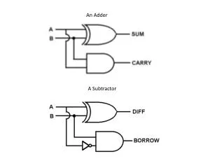
Serial Adder Description • Adds up values given over a length of time and computes the sum given. • This device is comprised of 4 components namely the adder itself, two shift registers for A and B, and a controller. • You have designed the adder component as previously given in the tutorial.
Shift Register Description • A shift register takes a std_logic_vector and outputs the bits serially each clock cycle. • Both A and B operand values should have an associated shift register. • Note that the contents of the shift register will be slowly feed to the adder one bit at a time. This is necessary since our adder can only take one bit at a time.
Controller Description • The controller component of the design simply acts as a logic diagram controlling which state the machine is in. • In the serial adder case there are three states • Idle – Machine is waiting • Loading – Machine is loading the shift registers • Shifting – The machine is dumping information from the shifters to the adder component
Putting it Together • Given the description above our design looks like this. Note that all devices are clocked (Not shown) Sum A A-bit Shift register A Full Adder B B-bit Carry Out Shift register B Done Sel En Reset Controller Go
Putting it all Together • Previous wiring diagram is difficult to simulate since there are so many components and internal signals. • Notice that there are only 6 ports that connect with outside devices. • Wouldn’t it be nice if we could package these components into a single black box for testing…..
Component Declarations • Instance components into a master VHDL file. • Saves time and is very straight forward. Format for this file is given below. Entity Declaration – similar as before Architecture Declaration -- Define components here -- Define internal wirings Begin -- instance components in design with port map End Architecture Declaration;
Component Declarations • Component declaration is nearly same as the device’s entity declaration. • Simply Copy and Paste in the component descriptions and add the key word component. Entity serial_adder is generic(N : natural := 8); port (a,b,clk,en : IN std_logic ; s : OUT std_logic_vector (N-1 DOWNTO 0); cout, done : OUT std_logic ); end serial_adder; Component serial_adder generic(N : natural := 8); port (a,b,clk,en : IN std_logic ; s : OUT std_logic_vector (N-1 DOWNTO 0); cout, done : OUT std_logic ); end component;
Internal Signals and Port Mappings • Internal wiring is done with signals. Simply declare these signals like you have done in previous exercises. • Port mapping is the where the actual components are instantiated and mapped to their respective signals. • Note that you can instantiate more then one instance of each component.
Example of Port Mapping • Let’s say you want to make a master VHDL design from the two components on the right. C Component -- Signal Declarations Signal N : std_logic; Signal M : std_logic; Begin -- Port Map Declarations My_A : Acomp generic map(N) port map(N,M,ck); My_B : Bcomp generic map(N) port map(M,N,ck); Ck A Component M N B Component