Download

1 / 18
180 likes | 357 Vues
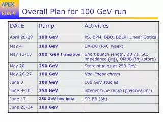
ATF2 plan for Autumn-Winter run. IWLC 2010 2010 / 10 /21 Toshiyuki OKUGI, KEK. The main purpose of the ATF2 operation in 2010 autumn / 2011 winter run. Investigation of the reason why the final beam size was 300nm (design 114nm) at the continuous operation in 2010 spring

E N D
ATF2 plan for Autumn-Winter run IWLC 2010 2010 / 10 /21 Toshiyuki OKUGI, KEK
The main purpose of the ATF2 operation in 2010 autumn / 2011 winter run • Investigation of the reason why the final beam size was 300nm • (design 114nm) at the continuous operation in 2010 spring • To make small vertical beam size as small as possible. • Preparation of ATF2 stage 2
In 2010 spring run, we performed 1st trial of the ATF2 continuous operation with 4cm bx and 1mm by optics. In the continuous operation, we achieved the 0.87 of the modulation depth at 8.0 deg. Mode. The evaluated vertical beam size is 310 +/- 30 (stat.) +0-/40 (syst.) nm. ( The design beam size is 114nm )
The candidate reason not to make the design beam size • Imperfect of the beam size tuning • The effect of multi-pole fields of FD magnets • The effect of the beam jitter • - We did not have the BPM at IP in 2010 spring run • 4. The effect of IP-BSM measurement • - The drift of the measured beam size was large in 2010 spring run
The minimum beam size was achieved after the vertical position optimization of individual FF sextupoles. I believe the vertical position of FF sextupoles were not so bad at the continuois operation
The b* also checked to be design beta function at the beginning of the continuous operation with post-IP WS. When Mark applied the IP beam size magnification knob, the measured beam size was not reduced. I believe the beta matching was not main reason why the measured beam size was not so small. However, we need to check with careful beam tuning. ( Continuous operation is important in coming beam operation period ! ) However, we have never change the strength of FF sextupoles to check the chromaticity and geometric aberration. We need to scan the strength of FF sextupoles in 2010 autumn run.
To confirm the amount of the beam jitter, • we installed the IP-BPM. • Installation of IP-BPM • IP-BPM installed • BPM cables are connected in the cable • Cabling work was finished - We performed the cavity BPM with 8.7nm resolution. - The resolution was excluded the effect of the coupling of X and off-phase(Q). - The effect of the off-phase(Q) is large for the beam large divergence.
BPM resolution test in 2008 Presented by Y.Honda ( 2010 / 7 /21 )
Presented by Y.Honda 2010 / 7 /21 Beam divergence ; 460 urad -> resolution is increased 25nm -> 80nm Beam divergence at ATF2 design optics ey=20pm -> sy’=450urad
KEK IP-BPM Thinner gap than FFTB cavity BPM We expect the effect of the beam divergence is smaller then FFTB cavity BPM. We expected 30nm (no divergence effect) - 80nm (same to FFTB) resolution, including the effect of coupling of X and off-phase(Q). It is enough to use for 100nm beam. The resolution study at large divergence beam ( i.e. ATF2 IP) is important to measure the fine beam position at ATF2 IP for the design beta_y optics.
Improvement of IP-BSM • Installation of the phase jitter monitor for the IP-BSM laser • 2. Improvement of timing jitter monitor of the IP-BSM laser trigger • When the trigger timing is jumped by 1count (2.8ns), • the gamma-ray signal was reduced to be 70% of the peak signal. We will be able to monitor the drift of the IP-BSM laser position. GUN station DRstation Kicker station IP-BSM station TDC TDC TDC Several TDCs will be installed and be monitored in the beam size measurement in order to identify the module with the timing jump.
Beam Optics Optimization We must fix the beam optics by the following criteria • Background condition to IP-BSM detector • Effect of multipole error for QEA magnets Presented by G.White at ATF2 meeting (10/06/2010) • Large beta_x (1cm) optics • Reoptimized sextupole strength
Plan of 2010 autumn / 2010 winter run for ATF2 stage1 2010 autumn • Initial commissioning of IP-BPM ( 30-80nm resolution) • Background study of nominal beta_y optics • Define the beam optics in the 2010 autumn operation and later • Investigation of the reason why the final beam size was larger • than the design beam size at the continuous operation in 2010 spring • 5. Squeeze the beam size as small as possible • IP-BPM resolution study for large divergence beam • Concentrate to squeeze the beam size to design beam size 2011 spring
Plan of 2010 autumn / 2010 winter run to ATF2 stage2 We will have to perform the following study item as preparation of ATF2 stage 2 as well as the small beam size generation. • Establishment of the stable multibunch beam generation • Establishment of the stable multibunch beam extraction (Fast Kicker) • Establishment of the technology of intra-train feedback (FONT)
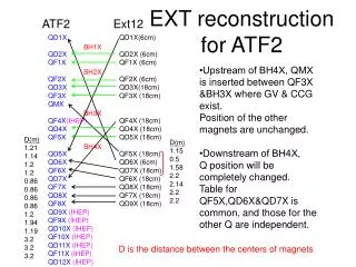
The sensitivity of the multipole fields The amount of the multi-pole fields to increase the vertical beam size to 300nm for the beam with1nm horizontal emittance and10pm vertical emittance QF1FF is the most sensitive for all of the multi-pole fields.
Remeasurement of FD magnet • We could not measure the multipole errors for FD magnet, • because we don’t have an appropriate rotating coil in KEK. • Therefore, we perform the following measurement • Resistance check of all coils to check the shortage of the coils • We could not find any coil shortage in this measurement. • 2. Geometrical measurement of FD magnet pole • QF1 rotations are -6.25mrad at E-end (upstream) and -4.09mrad at W-end. • Average is -5.17mrad. -> Twisted ! • QD0 rotations are +2.69mrad at E-end (upstream) and +2.79mrad at W-end. • Average is +2.74mrad.