Download
1 / 27
270 likes | 295 Vues
Explore microarchitectural strategies to minimize interconnect power and enhance efficiency in clustered processors, balancing latency and power tradeoffs effectively.

E N D
Power and Temperature-Aware Microarchitecture Microarchitectural Techniques to Reduce Interconnect Power in Clustered Processors Karthik Ramani Naveen Muralimanohar Rajeev Balasubramonian University of Utah
Motivation • Wire delays do not scale as well as their transistor counterparts • Communication bound future processors • Increased use of interconnects and hence, an increase in power dissipation • 50% of dynamic power is in interconnect switching (Magen et al. SLIP 04) • MIT Raw processor’s on-chip network consumes 36% of total chip power (Wang et al. 2003)
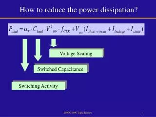
Interconnect Power • Reduction in power Increase in latency • Dynamic Power = aCV2f • Different Methods • Frequency scaling • Voltage scaling • Reducing the size of repeaters • Reducing the no. of repeaters
Power-Delay Tradeoff • Conventional Interconnect Design – Performance Oriented • Low latency • High Power Dissipation • Power Reduction by tolerating some delay penalty • Reducing Repeater Size L D SC • Decreasing No. of Repeaters L D SC Latency increases
Power Reduction Ref: Banerjee et al. IEEE Transactions on Electron Devices 2002
Impact of Power-centric Design • Delay Optimized Case – Wires optimized for delay • Power Optimized case – Wires optimized for power • Performance difference 20%
Heterogeneous Interconnects • Proposed Design – Implementing wires with varied characteristics • Delay optimized interconnect • Power optimized interconnect • Latencies twice the delay optimal wires • 80% reduction in power (by focusing on repeaters alone)
Outline • Motivation & Proposed solution • Base Architecture • Interconnect Transfers • Results • Conclusion & Future work
Architecture for evaluation D-cache • A dynamically scheduled clustered model with 16 clusters • Hierarchical interconnects • Crossbar • Ring • Centralized front-end • I-Cache & D-Cache • LSQ • Branch Predictor • Four FU/cluster I-Cache Cluster LSQ Cross bar (1 cycle latency) Ring interconnect (4 cycle latency)
Simulator Parameters • Simplescalar with contention modeled in detail • 15 entry o-o-o issue queue in each cluster (int & fp each) • 30 Physical registers (int & fp each) • In-flight window - 480 instructions • Inter-cluster latencies • Delay optimized 2-10 cycles • Power optimized 4-20 cycles
Interconnect transfers - Types Address transfer Ready register value Store value Bypassed register value Load value
Bypassed Register Values Producing Instruction completing execution at cycle 120 • Operands produced in a cluster that are immediately required by another cluster • Criticality based on two factors • Operand arrival time at the cluster • Actual issue time of the sourcing instruction • Criticality changes at runtime Regfile IQ FU Regfile Rename & Dispatch IQ FU Regfile IQ FU Needs a dynamic predictor Consumer Instruction dispatched at Cycle 100
The Data Criticality Predictor • A table indexed by the lower order bits of the instruction address, updated dynamically to indicate the criticality of data. • Difference in arrival time and usage calculated for each operand of an instruction • Difference < Threshold Critical • Difference > Threshold Non-Critical
Ready Register Values Regfile • Source operands that are available at the time of dispatch • Premise - significant latency between dispatch and issue • Latency tolerant Power optimized wires IQ FU Operand is ready at cycle 90 Regfile Rename & Dispatch IQ FU Regfile IQ FU Consumer instruction Dispatched at cycle 100 Regfile IQ FU
Load & Store data • Store data – Often non-critical • Impact of delayed stores (rare cases) • Dependent loads have to wait • Stall in the commit process if store is at the head of the reorder buffer • Latency insensitive – Power optimized network • Load data – Critical! • Often on the critical path • Latency sensitive – Fast network
Address prediction • High confidence prediction for 51% of effective address transfers L1 Cache LSQ FU Reg L1 Cache LSQ FU AP Reg
Outline • Motivation & Proposed solution • Base Architecture • Interconnect Transfers • Simulation results • Conclusion
Methodology Three cases for simulation • High Performance case – A clustered model with only delay optimized wires • Low Power case – A clustered model with all power-optimized wires • Criticality based case – A clustered model using heterogeneous wires
Results • Performance loss in criticality based case compared to high performance case 2.5% • Performance loss in low power case compared to high performance case is 20%
Results % IPC loss % Non-critical transfers
Summary of non-critical interconnect transfers Effective address predicted Unpredicted address Load value Ready register Store value Bypassed critical Bypassed non-critical
Result summary • Two kinds of non-critical transfers • Data that are not immediately used – 38% • Verification of address predictions – 13% • Criticality based case • 49% of all data transfers through the Power-optimized wires • Performance penalty - only 2.5% • Potential energy savings of around 50% in the interconnects
Related Work • Proposal of several heuristics for data criticality – Tune et al. [HPCA -7] , Srinivasan et al. [ISCA-28] • Redirection of instructions to units based on criticality – Seng et al. [MICRO 2001] • Balasubramonian et al. evaluated heterogeneous cache banks [MICRO 2003] • Banerjee and Mehrotra came up with an analytical model for designing interconnect for a given delay penalty [IEEE Trans. 2002]
Future Work • Other metrics for data criticality prediction (low confidence branch) • Application of heterogeneous interconnect in other places of the microprocessor (cache etc.) • Other configurations of heterogeneous interconnect
Conclusion • Single interconnect model optimized for delay or power alone is not enough • Heterogeneous interconnect model alleviates this problem • Criticality predictor efficiently identifies non-critical data • 49% goes in non-critical network – performance loss 2.5%
Thank You Questions ?