LM 555 Timer
LM 555 Timer. As an Astable Multivibrator. LM 555 Timer Chip. An integrated chip that is used in a wide variety of circuits to generate square wave and triangular shaped single and periodic pulses. Examples in your home are high efficiency LED and fluorescence light dimmers and


LM 555 Timer
E N D
Presentation Transcript
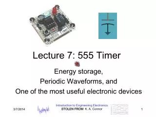
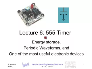
LM 555 Timer As an AstableMultivibrator
LM 555 Timer Chip • An integrated chip that is used in a wide variety of circuits to generate square wave and triangular shaped single and periodic pulses. • Examples in your home are • high efficiency LED and fluorescence light dimmers and • temperature control systems for electric stoves • The Application Notes section of the datasheet for LM 555 timer has a number of other circuits that are in use today in various communications and control circuits.
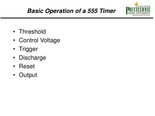
Two Types of Multivibrators • Monostable • A single pulse is outputted when an input voltage attached to the trigger pin of the 555 timer equals the voltage on the threshold pin. • Astable • A periodic square wave is generated by the 555 timer. • The voltage for the trigger and threshold pins is the voltage across a capacitor that is charged and discharged through two different RC networks. I know – who comes up with these names?
How a 555 Timer Works • We will operate the 555 Timer as an AstableMultivibrator in the circuit for the metronome. http://www.williamson-labs.com/480_555.htm
The components that make up a LM 555 timer are shown within the gray box. Two voltage comparators that are internal to the LM 555 determine the state of a D flip-flop. http://www.williamson-labs.com/480_555.htm
Voltage Comparator • As a reminder, an Op Amp without a feedback component is a voltage comparator. • Output voltage changes to force the negative input voltage to equal the positive input voltage. • Maximum value of the output voltage, Vo, is V+ if the negative input voltage, v1, is less than the positive input voltage, v2. • Minimum value of the output voltage, Vo, is V- if the negative input voltage, v1, is greater than the positive input voltage, v2.
The voltage comparators monitor the voltage across the capacitor to keep it between 1/3 -2/3 Vcc. The output of the lower voltage comparator will be V+ (Vcc) when the voltage across the capacitor is less than 1/3 Vcc, which is the voltage drop across the third resistor in the series of three resistors, which all have the same magnitude and are internal to LM 555. The output of the upper voltage comparator will be V- (0 V) when the voltage across the capacitor is more than 2/3 Vcc, which is the voltage drop across the middle resistor. http://www.williamson-labs.com/480_555.htm
The bipolar transistor (BJT) acts as a switch. http://www.williamson-labs.com/480_555.htm
Transistor • As you will learn in ECE 2204, a bipolar transistor can be designed to act like a switch. • When a positive voltage is applied to the base of the transistor (B), the transistor acts like there is a very small resistor is between the collector (C) and the emitter (E). • When ground is applied to the base of the transistor (B), the transistor acts like there is a an open circuit between the collector (C) and the emitter (E).
The transistor inside the LM 555 switches the voltage at pin 7, Discharge, on the DIP package to ground (or very close to 0 V), when Qbar (the Q with a line over it) of the D flip-flop is high and the voltage at Qbar is equal to 5 V. This forces the node voltage between Ra and Rb, the resistors external to the LM 555, to be 0 V. The capacitor is disconnected from Vcc and discharges through Rb to the path to ground that was formed when the transistor switches on. When the transistor is switched off, it acts like an open circuit. Vcc is now connected to the capacitor through Ra and Rband the capacitor is charged. http://www.williamson-labs.com/480_555.htm
The RC network when discharging the capacitor is RbC. The transistor will only be switched on when the voltage across the capacitor is more than 1/3 Vcc. When it decreases to this value, the output of the lower voltage comparator will change, setting the D flip-flop, which will cause Qbar = 0 V and the transistor will switch to an open circuit. http://www.williamson-labs.com/480_555.htm
The RC network when discharging the capacitor is (Ra+ Rb)C. The transistor will only be switched on when the voltage across the capacitor is less than 2/3 Vcc. When it increases to this value, the output of the upper voltage comparator will change, resetting the D flip-flop, which will cause Qbar = 5 V and the transistor will switch on. This will cause the capacitor to start discharging again. Thus, the voltage of the capacitor can be no more than 2/3 Vcc and no less than 1/3 Vccif all of the components internal and external to the LM 555 are ideal. http://www.williamson-labs.com/480_555.htm
The output of the 555 timer, pin 3, is Q on the D flip-flop. • When Qbar is 5 V and the capacitor is charging, Q is 0 V. • When Qbar is 0 V and the capacitor is discharging, Q is 5 V. • Thus, the output of a 555 timer is a continous square wave function (0 V to 5 V) where: • the period is dependent the sum of the time it takes to charge the capacitor to 2/3 Vcc and the time that it takes to discharge the capacitor to 1/3 Vcc. • In this circuit, the only time that the duty cycle (the time that the output is at 0 V divided by the period) will be 0.5 (or 50%) is when Ra = 0 W, which should not be allowed to occur as that would connect Vcc directly to ground when the transistor switches on. http://www.williamson-labs.com/480_555.htm