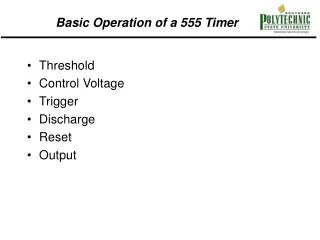
Introduction to Periodic Waveforms and 555 Timer Circuits
Learn about physical periodic motion and phenomena, generating audio signals from temperature data, using models for simulations, and working with capacitor charging in 555 timer circuits. Understand the principles of Astable and Monostable Multivibrators.


Introduction to Periodic Waveforms and 555 Timer Circuits
E N D
Presentation Transcript
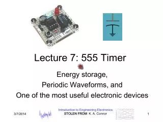
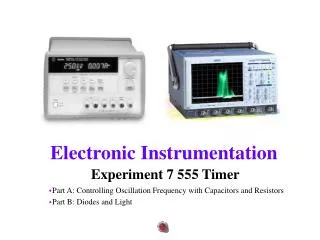
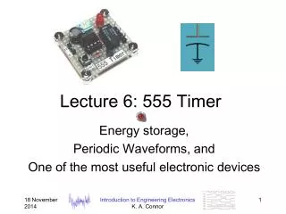
Lecture 7: 555 Timer Energy storage, Periodic Waveforms, and One of the most useful electronic devices Introduction to Engineering Electronics STOLEN FROM K. A. Connor
Examples of Physical Periodic Motion • Pendulum • Bouncing ball • Vibrating string (stringed instrument) • Circular motion (wheel) • Cantilever beam (tuning fork) Introduction to Engineering Electronics STOLEN FROM K. A. Connor
Other Periodic Phenomena • Daily cycle of solar energy • Annual cycle of solar energy • Daily temperature cycle • Annual temperature cycle • Monthly bank balance cycle • Electronic clock pulse trains • Line voltage and current Introduction to Engineering Electronics STOLEN FROM K. A. Connor
Daily Average TemperatureAlbany-Troy-Schenectady • Data (blue) covers 1995-2002 • Note the sinusoid (pink) fit to the data Introduction to Engineering Electronics STOLEN FROM K. A. Connor
Using Matlab to Produce Audio Signal from Daily Average Temps • Data is normalized to mimic sound • Data is filtered to find fundamental Introduction to Engineering Electronics STOLEN FROM K. A. Connor
Matlab Window Introduction to Engineering Electronics STOLEN FROM K. A. Connor
Periodic Pulse Train from a 555 Timer • This circuit puts out a steady state train of pulses whose timing is determined by the values of R1, R2 and C1 • The formula has a small error as we will see Introduction to Engineering Electronics STOLEN FROM K. A. Connor
Using Models • Recall that you should use a model that you understand and/or know how to properly apply • To use it properly • Check for plausibility of predicted values (ballpark test). Are the values in a reasonable range? • Check the rate of changes in the values (checking derivative or slope of plot). • Are the most basic things satisfied? • Conservation of energy, power, current, etc. • Developing a qualitative understanding of phenomena now will help later and with simulations. Introduction to Engineering Electronics STOLEN FROM K. A. Connor
Charging a Capacitor • Capacitor C1 is charged up by current flowing through R1 • As the capacitor charges up, its voltage increases and the current charging it decreases, resulting in the charging rate shown Introduction to Engineering Electronics STOLEN FROM K. A. Connor
Charging a Capacitor • Capacitor Current • Capacitor Voltage • Where the time constant Introduction to Engineering Electronics STOLEN FROM K. A. Connor
Charging a Capacitor • Note that the voltage rises to a little above 6V in 1ms. Introduction to Engineering Electronics STOLEN FROM K. A. Connor
Charging a Capacitor • There is a good description of capacitor charging and its use in 555 timer circuits at http://www.uoguelph.ca/~antoon/gadgets/555/555.html Introduction to Engineering Electronics STOLEN FROM K. A. Connor
2 Minute QuizName______Section_____Date_____True or False? • If C1 < C2, for a fixed charging current, it will take longer to charge C1 than C2 Introduction to Engineering Electronics STOLEN FROM K. A. Connor
555 Timer • At the beginning of the cycle, C1 is charged through resistors R1 and R2. The charging time constant is • The voltage reaches (2/3)Vcc in a time Introduction to Engineering Electronics STOLEN FROM K. A. Connor
555 Timer • When the voltage on the capacitor reaches (2/3)Vcc, a switch is closed at pin 7 and the capacitor is discharged to (1/3)Vcc, at which time the switch is opened and the cycle starts over Introduction to Engineering Electronics STOLEN FROM K. A. Connor
555 Timer • The capacitor voltage cycles back and forth between (2/3)Vcc and (1/3)Vcc at times and Introduction to Engineering Electronics STOLEN FROM K. A. Connor
555 Timer • The frequency is then given by Note the error in the figure Introduction to Engineering Electronics STOLEN FROM K. A. Connor
Inside the 555 • Note the voltage divider inside the 555 made up of 3 equal 5k resistors Introduction to Engineering Electronics STOLEN FROM K. A. Connor
555 Timer • These figures are from the lab write up • Each pin has a name (function) • Note the divider and other components inside Introduction to Engineering Electronics STOLEN FROM K. A. Connor
Astable and Monostable Multivibrators • Astable puts out a continuous sequence of pulses • Monostable puts out one pulse each time the switch is connected Introduction to Engineering Electronics STOLEN FROM K. A. Connor
Astable and Monostable Multivibrators • What are they good for? • Astable: clock, timing signal • Monostable: a clean pulse of the correct height and duration for digital system Introduction to Engineering Electronics STOLEN FROM K. A. Connor
Optical Transmitter Circuit Astable is used to produce carrier pulses at a frequency we cannot hear (well above 20kHz) Introduction to Engineering Electronics STOLEN FROM K. A. Connor
Optical Receiver Circuit • Receiver circuit for transmitter on previous slide Introduction to Engineering Electronics STOLEN FROM K. A. Connor
2 Minute QuizName______Section_____Date_____True or False? • If R1 < R2, for a fixed charging voltage, it will take longer to charge a given capacitor C through R1 than R2 Introduction to Engineering Electronics STOLEN FROM K. A. Connor
Clapper Circuit • Signal is detected by microphone • Clap is amplified by 741 op-amp • Ugly clap pulse triggers monostable to produce clean digital pulse • Counter counts clean pulses and triggers relay through the transistor Introduction to Engineering Electronics STOLEN FROM K. A. Connor
555 Timer Applications • 40 LED bicycle light with 20 LEDs flashing alternately at 4.7Hz Introduction to Engineering Electronics STOLEN FROM K. A. Connor
555 Timer Applications • 555 timer is used to produce an oscillating signal whose voltage output is increased by the transformer to a dangerous level, producing sparks. • DO NOT DO THIS WITHOUT SUPERVISION Introduction to Engineering Electronics STOLEN FROM K. A. Connor
Tank Circuit: A Classical Method Used to Produce an Oscillating Signal • A Tank Circuit is a combination of a capacitor and an inductor • Each are energy storage devices Introduction to Engineering Electronics STOLEN FROM K. A. Connor
Tank Circuit: How Does It Work? • Charge capacitor to 10V. At this point, all of the energy is in the capacitor. • Disconnect voltage source and connect capacitor to inductor. • Charge flows as current through inductor until capacitor voltage goes to zero. Current is then maximum through the inductor and all of the energy is in the inductor. Introduction to Engineering Electronics STOLEN FROM K. A. Connor
Tank Circuit • The current in the inductor then recharges the capacitor until the cycle repeats. • The energy oscillates between the capacitor and the inductor. • Both the voltage and the current are sinusoidal. Introduction to Engineering Electronics STOLEN FROM K. A. Connor
Tank Circuit Voltage and Current Introduction to Engineering Electronics STOLEN FROM K. A. Connor
Tank Circuit • There is a slight decay due to finite wire resistance. • The frequency is given by (period is about 10ms) Introduction to Engineering Electronics STOLEN FROM K. A. Connor
Tank Circuit • Tank circuits are the basis of most oscillators. If such a combination is combined with an op-amp, an oscillator that produces a pure tone will result. • This combination can also be used to power an electromagnet. • Charge a capacitor • Connect the capacitor to an electromagnet (inductor). A sinusoidal magnetic field will result. • The magnetic field can produce a magnetic force on magnetic materials and conductors. Introduction to Engineering Electronics STOLEN FROM K. A. Connor
2 Minute QuizName______Section_____Date_____True or False? • When a capacitor C is connected to a battery through a resistor R, the charging current will be a maximum at the moment the connection is made and decays after that. Introduction to Engineering Electronics STOLEN FROM K. A. Connor
Tank Circuit Application • In lab 10 we will be using the circuit from a disposable camera. • We can also use this type of camera as a power source for an electromagnet. Introduction to Engineering Electronics STOLEN FROM K. A. Connor
Disposable Camera Flash Capacitor Connected to a Small Electromagnet Introduction to Engineering Electronics STOLEN FROM K. A. Connor
Disposable Camera Flash Experiment/Project • A piece of a paperclip is placed part way into the electromagnet. • The camera capacitor is charged and then triggered to discharge through the electromagnet (coil). • The large magnetic field of the coil attracts the paperclip to move inside of the coil. • The clip passes through the coil, coasting out the other side at high speed when the current is gone. Introduction to Engineering Electronics STOLEN FROM K. A. Connor
Coin Flipper and Can Crusher • The can crusher device crushes a soda can with a magnetic field. Introduction to Engineering Electronics STOLEN FROM K. A. Connor
Can Crusher and Coin Flipper • This is an animation a student made as a graphics project a few years ago Introduction to Engineering Electronics STOLEN FROM K. A. Connor
Can Crusher and Coin Flipper • For both the can crusher and coin flipper, the coil fed by the capacitor acts as the primary of a transformer. • The can or the coin acts as the secondary. • A large current in the primary coil produces an even larger current in the can or coin (larger by the ratio of the turns in the primary coil) • The current in the coin or can is such that an electromagnet of the opposite polarity is formed (Lenz’ Law) producing two magnets in close proximity with similar poles facing one another. • The similar poles dramatically repel one another Introduction to Engineering Electronics STOLEN FROM K. A. Connor
Magnetic Launchers • Coilguns/Railguns Introduction to Engineering Electronics STOLEN FROM K. A. Connor
Coilguns & Railguns • Two types of launchers are being developed for a variety of purposes. Introduction to Engineering Electronics STOLEN FROM K. A. Connor
Where Will You See This Material Again? • Electromagnetic Fields and Forces: Fields and Waves I • 555 Timers: Many courses including Analog Electronics and Digital Electronics • Oscillators: Analog electronics • Clocks, etc: Digital Electronics, Computer Components and Operations, and about half of the ECSE courses. Introduction to Engineering Electronics STOLEN FROM K. A. Connor
Appendix Introduction to Engineering Electronics STOLEN FROM K. A. Connor
Using Conservation Laws to Derive Fundamental Equations • Energy stored in capacitor plus inductor • Total energy must be constant, thus Introduction to Engineering Electronics STOLEN FROM K. A. Connor
Using Conservation Laws • Simplifying • This expression will hold if • Noting that Introduction to Engineering Electronics STOLEN FROM K. A. Connor
Using Conservation Laws + + I VC VL • Note that for the tank circuit • The same current I flows through both components • The convention is that the current enters the higher voltage end of each component Introduction to Engineering Electronics STOLEN FROM K. A. Connor
Using Conservation Laws • Experimentally, it was also determined that the current-voltage relationship for a capacitor is • Experimentally, it was also determined that the current-voltage relationship for an inductor is Introduction to Engineering Electronics STOLEN FROM K. A. Connor
Using Conservation Laws • Applying the I-V relationship for a capacitor to the expressions we saw before for charging a capacitor through a resistor • We see that Introduction to Engineering Electronics STOLEN FROM K. A. Connor
Using Conservation Laws • Simplifying • Which is satisfied if • The latter is the relationship for a resistor, so the results work. Introduction to Engineering Electronics STOLEN FROM K. A. Connor