Download
1 / 41
430 likes | 1.08k Vues
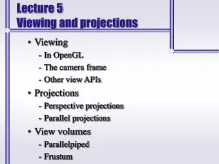
Viewing and Projections . Aknowledgements: to my best knowledges, these slides originally come from University of Washington, and are subsequently adapted by colleagues. Reading. Required: Hill Chapter 7 OpenGL Programming Guide (the red book) Chapter 3. 3D Geometry Pipeline.

E N D
Viewing and Projections Aknowledgements: to my best knowledges, these slides originally come from University of Washington, and are subsequently adapted by colleagues.
Reading Required: • Hill Chapter 7 • OpenGL Programming Guide (the red book) Chapter 3
3D Geometry Pipeline • Before being turned into pixels, a piece of geometry goes through a number of transformations…
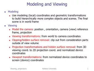
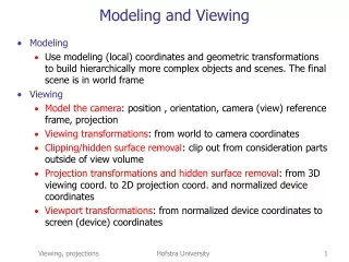
3D graphics coordinate systems • Local coordinate system (or space) • (object coordinates, modeling coordinates): • objects • (global) world coordinate system: • scene descrition and lighting definition • Modeling transformation (similarity transformation) • Camera-centered coordinate system • view-reference coordinate system, or eye-coordinate system, 3D view space, • projective transformation • Normalized (3D) camera-centered coordinate system • Normalized 3D view space for a given ‘view volume’ (or canonical 3D view space, 3D screen coordinates): • x = [-1,1], y = [-1,1], z = [0,-1] for parallel projection • Six planes: x = +/- z, y = +/- z, z=-z_min, and z=-1 for perspective. • Image-coordinate system • (2D device coordinate system, screen coordinates, raster coordinates)
OpenGL viewing • Modelview transformation • Modeling transformation: model local coordinates world coordinates • Viewing transformation: world coordinates eye coordinates
OpenGL viewing • Viewing transformation • gluLookAt(eye.x, eye.y, eye.z, center.x, center.y, center.z, up.x, up.y, up.z) • Viewing direction: center – eye • Up is the upward direction • Viewing direction and up vector eye coordinate system • X axis points to the right of viewer • Y axis points upward • Z axis points to the back of viewer • Generate a matrix, which is postmultiplied to the top-of-the-stack matrix on the Modelview stack • Thus, must be called before any modeling transformations
OpenGL viewing • Default OpenGL viewing (if no gluLookAt is specified) • Eye is at origin of world space • Looking down the negative z axis of world space • Up vector is positive y axis • The viewing transformation matrix is identity matrix (i.e. eye coordinate system = world coordinate system)
The pinhole camera • The first camera – “camera obscura” – known to Aristotle. • In 3D, we can visualize the blur induced by the pinhole (a.k.a. aperture): • Q: How would we reduce blur?
Shrinking the pinhole • Q: What happens as we continue to shrink the aperture?
Imaging with the synthetic camera • In practice, pinhole cameras require long exposures, can suffer from diffraction effects, and give an inverted image. • In graphics, none of these physical limitations is a problem. The image is rendered onto an image plane (usually in front of the “camera”) Viewing rays emanate from the center of projection (COP) at the center of the pinhole. The image of an object P is at the intersection of the viewing ray through P and the image plane.
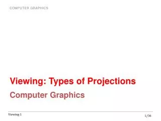
Projections • Projections transform points in n-space to m-space, where m<n. • In 3D, we map points from 3-space to the projection plane (PP) (a.k.a., image plane) along projectors (a.k.a., viewing rays) emanating from the center of projection (COP): • There are two basic types of projections: • Perspective – distance from COP to PP finite • Parallel – distance from COP to PP infinite
Parallel projections • For parallel projections, we specify a direction of projection (DOP) instead of a COP. • There are two types of parallel projections: • Orthographic projection – DOP perpendicular to PP • Oblique projection --- DOP not perpendicular to PP
Parallel projections • Orthographic projections along the z-axis in 3D • Ignoring the z component: • We can use shear to line things up when doing an oblique projection • We often keep the initial z value around for later use. Why?
Properties of parallel projection • Properties of parallel projection: • Not realistic looking • Good for exact measurements • Are actually a kind of affine transformation • Parallel lines remain parallel • Ratios are preserved • Angles not (in general) preserved • Most often used in CAD, architectural drawings, etc., where taking exact measurement is important
Derivation of perspective projection • Consider the projection of a point onto the projection plane: By similar triangles, we can compute how much the x and y coordinates are scaled:
Perspective projection • How to represent the perspective projection as a matrix equation? Is the matrix unique? • By performing the perspective divide, we get the correct projected coordinates:
Projective normalization • After applying the perspective transformation and dividing by w, we are free to do a simple parallel projection to get the 2D image. What does this imply about the shape of things after the perspective transformation + divide ?
Vanishing points • What happens to two parallel lines that are not parallel to the projection plane? • Think of train tracks receding into the horizon… • The equation for a line is: • After perspective transformation we get:
Vanishing points (cont’d) • Dividing by w: • Letting t go to infinity: • We get a point! • What happens to the line l = q + t v? • Each set of parallel lines intersect at a vanishing point on the Projection Plane. • Q: how many vanishing points are there?
Properties of perspective projections • Some properties of perspective projections: • Lines map to lines • Parallel lines do not necessarily remain parallel • Ratios are not preserved. • An advantage of perspective projection is that size varies inversely with distance – looks realistic. • A disadvantage is that we can’t judge distances as exactly as we can with parallel projections.
Summary What you should take away from this lecture: • The meaning of all the boldfaced terms • An appreciation for the various coordinate systems used in computer graphics • How the perspective transformation works • How we use homogeneous coordinates to represent perspective projections • The classification of different types of projections • The concept of vanishing points • The properties of perspective transformations
OpenGL projection • glOrtho(), gluPerspective() or glFrustum() • Produce a matrix which is stored in the projection matrix stack • All geometry objects are already transformed to the eye coordinate system before projection transformation is applied • The parameters of these functions are with respect to the eye coordinate system • The parameters define 6 clipping planes • To simplify clipping, the viewing space is transformed into a canonical view volume (all coordinates in [-1, +1])
OpenGL orthographic projection glOrtho(left, right, bottom, top, near, far) • left, right, bottom, top are coordinates in eye space • left, right are the x-coordinate limits • bottom, top are the y-coordinate limits • near, far are signed distances from the eye to the near and far clipping planes (e.g., near = 2, far = 15 mean the clipping planes are at z=-2 and z= -15)
OpenGL perspective projection • The center of projection and the portion of the projection plane that map to the final image form an infinite pyramid. The sides of the pyramid are clipping planes. • All of the clipping planes bound the viewing frustum. • In OpenGL, PP (projection plane) = near plane
OpenGL perspective projection glFrustum(left, right, bottom, top, near, far) • View frustum may not be centered along view vector • Less often used than gluPerspective() gluPerspective(fov_y, aspect_ratio, near, far) • fov_y is vertical field-of-view in degrees • aspect ratio = width / height • near, far are distances from eye to two clipping planes • must be positive • Keep them close so as to maximize depth precision
OpenGL perspective projection glFrustum(left, right, bottom, top, near, far) • The view frustum may not be centered along view vector • Less often used than gluPerspective() gluPerspective(fov_y, aspect_ratio, near, far) • fov_y is vertical field-of-view in degrees • aspect ratio = width / height • near, far are distances from eye to two clipping planes • must be positive • Keep them close so as to maximize depth precision
OpenGL perspective projection • In last lecture, we discuss projection with no depth • In graphics, we need depth for hidden surface removal – when two points project to the same point on the image plane, we need to know which point is closer • But, actual distance is cumbersome to compute • Sufficient to use pseudodepth • what is a good choice? Can we use z as pseudodepth? (farther point has more negative z value)
OpenGL perspective projection • Turns out that it is better to choose a function with same denominator as x and y so that it can be represented as matrix multiplication
OpenGL perspective projection • How to represent the perspective transformation as a matrix? • Then by perspective division: Perspective projection = perspective transformation + orthographic projection
OpenGL perspective projection • Choose a and b such that the pseudodepth z’ is in [-1, 1] • Note: before the transformation, farther objects have larger negative z; after transformation, farther objects have larger positive z values (involves a “reflection”)
OpenGL perspective projection • Lines through the eye are mapped into lines parallel to the z-axis The view frustum is transformed into a parallelepiped
OpenGL perspective projection • Include a scaling in both x and y to map to [-1,1] • Final matrix • The view frustum of glFrustum() may not be centered along the view vector, so it needs one more step to first shear the window.
gluPerspective() is more popular, easily convert into the previous matrix • General 4*4 matrix of the perspective projection
OpenGL Clipping in (x,y,z,w) • OpenGL performs clipping in homogeneous space (after perspective transformation, before perspective division) • objects in front of projection plane and behind the eye are clipped avoid division by zero • A point (x, y, z, w) with positive w (why?) is in the canonical view volume if • So in homogeneous space the clipping limits are But only for ‘point’, not for ‘triangle’, so a pre-processing.
Pixel-level processes with inhomogeneous (x,y,z) • Straightforward for a point, usually for each triangle of a mesh • Hiden-surface removal, interpolating z to get a depth for each pixel • Rasterization, interpolating vertices x • Shading, interpolating vertices intensities for each pixel
Z-buffer • Besides RGB values of a pixel, maintain some notion of its depth • An additional channel in memory, like alpha • Called z-buffer or depth buffer • Probably the simplest and most widely used (in hardware, e.g. GeForce cards) • When the time comes to draw a pixel, compare its depth with the depth of what’s already in the framebuffer. Replace only if it’s closer
Rasterization • The process of filling in the pixels inside of a polygon is called rasterization. • During rasterization, the z value and shade s can be computed incrementally (i.e., quickly, taking advantage of coherence) An algorithm exhibits coherence if it uses knowledge about the continuity of the objects on which it operates