Payload Subsystem Integration and Testing Report
This detailed report outlines the integration and testing processes for various payload subsystems developed by university teams. It covers the mission overview, functional block diagrams, integration procedures, testing results, and best practices learned during the project. Key findings related to subsystem communication, software functionality, and sensor calibration are documented, along with action items for future teams. Additionally, it includes visuals to illustrate the integration efforts and highlights any challenges faced, ensuring a thorough understanding of the tasks accomplished.

Payload Subsystem Integration and Testing Report
E N D
Presentation Transcript
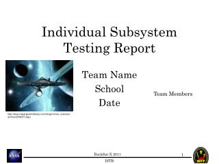
Payload Subsystem Integration and Testing Report Universities/Institutions Team Members Date
User Notes • This template shall be followed as closely as possible.
Mission Overview • Briefly remind everyone what your mission is.
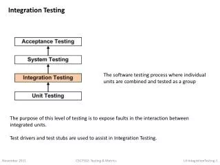
Functional Block Diagram • A Functional block diagram of the entire system should be presented here. • By now, your payload should have excellent block diagrams after CDR completion. • Use this diagram as a basis/reference as you explain to me how things integrated together. • Be sure to define subsystem acronyms
Integration Procedure • How did you integrate your various subsystems? • To what level (Full system or just subsystem to subsystem?) • i.e. • Power board verified, then connected to main board • Powered up main board and verified voltages at all sensors • Connected control board.... Blah, blah, blah • After testing electrical boards, mounted to RockSat-X plate • Mounted mechanical boom to plate • Connected mechanical boom to control board... Blah, blah, blah • Show pictures! I am hoping to see components fitting together Integrating the tether spool onto the power and unpowered hubs (EXAMPLE Picture and description)
Results • What went wrong? • What will be done to remedy the problem? • What lesson (if any) was learned? • Pictures! • What went right? • Pictures • Best practices • What advice could you give to next year’s team?
Integrated Subsystem Testing • Once integrated, did you test any of the integrated subsystems? • Why did you perform the test that you did? • If you didn’t test integrated subsystems, why not? • If you had a failure, which prevented testing, how will you move forward? • Pictures! Control board mounted to main board Testing functionality of push-button state changes in software (EXAMPLE)
Testing Results • Did everything work as planned? • Did all electronics communicate? • Did the software work with all subsystems? • Did the sensors return reasonable data? • Will the sensors need calibration? • Most importantly, just summarize your findings • What needs to change before flight? • Action items… Push-button Software Control: Success Successfully changed software states through push-buttons. No changes required for flight Main and Control boards could NOT be integrated into structure due hole misalignment. Next revision of board will have correct hole alignment. EXAMPLE
SITR to DITL 1 • What is your plan from now until your first Day In The Life (DITL) testing report?
Concluding Remarks • Issues and concerns • Closing remarks
Appendix • Additional data not immediately relevant to the presentation • You should include copies of updated: • Mechanical Drawings • Electrical Schematics • Power Budget • ICDs