Space Dust Collection System Testing Report
Detailed report on testing the subsystems for NASA's space dust collection mission. Includes design changes, parameters, and analysis of key components.

Space Dust Collection System Testing Report
E N D
Presentation Transcript
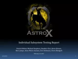
Individual Subsystem Testing Report Patrick Weber, Michael Stephens, Heather Choi, Kevin Brown, Ben Lampe, Anne-Marie Suriano, Eric Robinson, Dorin Blodgett February 24, 2011
Mission Overview 3 4 2 5 1 6 Presenter: Dorin Blodgett
Mission OverviewScientific Mission Primary: Collect space dust. • Particle size = nano and micro level • Space Dust Composition (10-6) • Exhausted Rocket Fuel • Meteor / Metal Fragments • Other Miscellaneous Gases • Donate collected aerogel tablets to UW Geology Department for further analysis Secondary: • Capture Detailed data throughout flight duration • Thermal Data • Seismic/Vibration Data • Earth images/video Presenter: Dorin Blodgett
Mission OverviewEngineering Mission Engineer an extendable boom to mount a dust collector. Use aerogel as dust collectors. Engineer modular electronic systems for: • Capturing and storing images from optical devices. • Actuating Telescopic Boom • Recording thermal and seismic data in real time throughout launch using sensors and transferring recording data via provided NASA Wallops Telemetry. Presenter: Dorin Blodgett
Mission OverviewConcept of Operations t ≈ 1.7 min Shedding of Skin Boom Extends via First Timed Event t ≈ 4.0 min Boom Retractsvia Arduino Controller Boom Power Shut Down t ≈ 2.8 min Apogee t ≈ 0.7 min End of Orion Burn t ≈ 15 min Splash Down Payload Power Down t ≈ 8.2 min Chute Deploys t ≈ 0 min Launch Systems Power On (t = -2 min) -Collection of Sensor Data Begins Presenter: Dorin Blodgett
Design DescriptionSubsystem Overview STR OC/STR Interface EPS/STR Interface Telemetry Wallops PWR Wallops Optical Camera Temp. Sensor Accel. Sensor IS/STR Interface Boom Boom Motor Optical Camera Arm Control MCU Aerogel TB/STR Interface EPS TB OC IS Control Box IS/EPS Interface OC/EPS Interface TB/EPS Interface Optical Camera Motor Temperature Sensor Accelerometers Presenter: Dorin Blodgett
Design Description/ Design Changes 3 4 2 5 1 6 Presenter: Dorin Blodgett
Design DescriptionNew Design Parameters Full Canister Available • 30 ± 1 lb weight requirement • Payload material changed to Steel • Payload – 16.7 lb • Ballast – 13.3 lb • Higher centrifugal forces • More powerful motor needed - holding torque of 57.6 lbin • Load increased on tape reel • Loading Stress – 16.5 ksi • Axial Deflection – 5.93E-4 in • Boom Seal • Tapered Seal • O-ring (Durometer Shore A:70) Presenter: Dorin Blodgett
Design DescriptionNew Design Parameters Skin Ejection • Clam-like skin shed after motor burn-out • Payload section will not be pressurized Temperatures at Reentry • Max of 350oF – well after apogee • Bearing material changed to Teflon • Higher operating temperature is 500F, melting of 635F • Radial thermal expansion, Δ T of 273F • Teflon = 3.3E-2 in • Steel = 3.3E-3 in • High temperature o-ring (A:70) • Aerogel cover over electric components Presenter: Dorin Blodgett
Design DescriptionNew Design Parameters Boom Vacuum • Boom will be pre-vacuumed prior to launch • Atmospheric pressures will ensure internal vacuum during reentry • Vacuum will aid in holding boom closed Aerogel Contamination • Aerogel tablets will be inserted in clean room • Boom will be vacuumed • Aerogel Properties • Pore Network is open Presenter: Dorin Blodgett
Design DescriptionProgram Management Project Manager Shawn Carroll Engineering Faculty Advisor Dr. Carl Frick Physics Faculty Advisor Dr. Paul Johnson Team Leader Patrick Weber Telescopic Boom (TB) Patrick Weber Eric Robinson Dorin Blodgett Electrical Power System (EPS) Michael Stephens Ben Lampe Integrated Sensors (IS) Michael Stephens Heather Choi Optical Camera (OC) Kevin Brown Nick Roder No Changes Presenter: Dorin Blodgett
Design DescriptionProgram Management Team Picture Presenter: Dorin Blodgett
Design DescriptionProgram Management Schedule Update • Manufacturing delay (approval for construction) • Electrical manufacturing is on schedule and has begun assembly Resolve Issues • Final drawings will soon be submitted to machine shop • Manufacturing should be done in two weeks Concerns • Will a vacuum/ clean room be available at Wallops? Presenter: Dorin Blodgett
Design Analysis Subsystem Updates 3 4 2 5 1 6 Presenter: Eric Robinson
Design AnalysisSubsystem List Telescopic Boom (TB) Optical Camera (OC) Integrated Sensors (IS) Electrical Power System (EPS) Presenter: Eric Robinson
Design Analysis - TBBoom Force Parameters Forces on Boom - Testing on Earth Presenter: Eric Robinson
Design Analysis - TBBoom Force Parameters Forces on Boom – Throughout Launch Presenter: Eric Robinson
Design Analysis -TBBoom Force Parameters Force Ranges through Launch Force Ranges through Reentry Presenter: Eric Robinson
Design Analysis -TBMotor Parameters Torque Load on Motor Throughout Launch Presenter: Eric Robinson
Design Analysis -TBNew Payload Design Presenter: Eric Robinson
Design Analysis - TBNew Payload Design Presenter: Eric Robinson
Design Analysis -TBPayload Boom Lengths • Retracted – • 11.4 in boom • Extended – • 27.1 in boom • 14.6 in reach Presenter: Eric Robinson
Design Analysis -TBTelescopic Boom - Stress Key Results Loading of 50G in all directions and 100G vertical impulses Presenter: Eric Robinson • Stress • Peak von Mises • ~1350 psi at Motor Support • Verified with Empirical Models
Design Analysis - TBTelescopic Boom – Deflection Key Results Loading of 50G in all directions and 100G vertical impulses Presenter: Eric Robinson • Deflection • Peak Deflection • 0.24 thousandths ofan inch • Occurs at center ofboom.
Subsystem Testing 3 4 2 5 1 6 Presenter: Patrick Weber
Subsystems Testing Tests to be Performed TB • Mechanical Test • Tape – reel buckling test Completed • Vibration test Not Completed • Drop impact test Not Completed • Water seal test Not Completed • Thermal expansion test Not Completed • Cyclic extension/retraction test Not Completed Presenter: Patrick Weber
Subsystems Testing Tests to be Performed EPS/ IS/OC • Electrical Test • Temperature sensor functionality test In Progress • Accelerometer functionality test Not Completed • Optical camera functionality test Not Completed • Thermal loading on electronics test Not Completed • Software Test • Asynchronous data capture test Not Completed • Motor control test Not Completed • Integration test Not Completed • Data recovery test Not Completed Presenter: Patrick Weber
Subsystems Testing - TBTape-reel Buckling Test Key Results (14” Tape – reel) Bucking Load with respect to Tape – reel Length Presenter: Patrick Weber • Extension load - earth • 0.23 lbf • Buckles loading of • 16.28 lbf
Subsystem Integration 3 4 2 5 1 6 Presenter: Patrick Weber
Subsystem IntegrationPlan Based on where you are now, how will you ensure the subsystems will be integrated and tested for the Subsystem Integration and Testing Report? • Manufacture Payload • Assembly Payload • Test Payload What are the major hurdles going to be? • Approval for Construction/ME Faculty • Part Backorder/Wait Time Presenter: Patrick Weber
Subsystem IntegrationLessons Learned What have you learned about subsystem testing and engineering so far? • The payload is over-engineered What would you do differently? • Push ME Faculty harder for approval for construction What has worked well so far? • We have analytical justification for all models Presenter: Patrick Weber
Fabrication and Assembly 3 4 2 5 1 6 Presenter: Patrick Weber
Fabrication and AssemblyMechanical Fabrication Payload Frame – 1018 Carbon Steel • CNC machined • Bolted down to base Telescopic Boom –1018 Carbon Steel • Boom Housing • Tubing epoxied into frame • Intermediate Arm • Threaded tubing and bearing mounts • Teflon bearing • Aerogel Arm • CNC machined • Aerogel Purchased • Tape Reel housing • CNC machined • Bolted to frame Presenter: Patrick Weber
Fabrication and AssemblyMechanical Assembly Manufacturing Instructions Presenter: Patrick Weber
Detailed Mass Budget Total Mass Budget (30±1 lbs) • Structure (16.7 lbs) • Boom (13.7 lbs) • Circuit Trays (2.99 lbs) • Camera (0.25 lb) • Other Sensors (1 lb) • Modular Electrical System (1 lb) • Ballasting (13.3 lbs) Presenter: Patrick Weber
Monetary Budget Monetary Budget (~$1300) • Structure ($675) • Boom ($300) • Aerogel ($375) • Camera ($100) • Other Sensors ($110) • Modular Electrical System ($225) • Contingency (+$15%) Presenter: Patrick Weber
Conclusions 3 4 2 5 1 6 Presenter: Patrick Weber
Conclusions New Design Parameters Effects on Design • Reentry temperatures of 350oF – Teflon Bearings • Boom vacuum created before launch and at reentry • Prevent aerogel contamination • Full canister available • Payload made of 1018 Carbon Steel – • Less ballasting but greater centrifugal forces • Motor must withstand a holding torque of 57.6 lbin • New tape reel and frame design will survive loadings Fabrication and Assembly Vacuum/Clean room availability Presenter: Patrick Weber