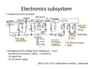
Energy and Timing Resolution of Detector DAQ Subsystem for Nuclear Physics Research
This project entails designing and testing a Detector DAQ subsystem for nuclear physics research, focusing on energy and timing resolution improvements. Detailed specifications include waveform readout, offline pulse shape analysis, coincidences detection, TOF measurements, and more.

Energy and Timing Resolution of Detector DAQ Subsystem for Nuclear Physics Research
E N D
Presentation Transcript
DAQ Subsystem Christopher Crawford University of Kentucky Robert Grzywacz University of Tennessee April 18 2012 DoE, Germantown MD
Data Collection WBS Elements • 1.10 Data collection systems $426k + 25% • 1.10.01 Detector Readout Electronics $349k + 23% • 1.10.02 Slow Control $ 4k + 20% • 1.10.03 HV System $ 73k + 36% • * Covered by DOE Project funds Detector DAQ in its Faraday Cage (WBS 1.10)
WPS 1.10.01 Detector Readout Electronics $349k + 25% Scope: • Read out waveform (energy + timing) of each pixel 2 x 128 ch. • offline pulse shape analysis for improved resolution and PID • Form e-p coincidences • 50 – 750 keV prompt electron • 30 keV proton (HV) delayed by 12 – 40 μs TOF • Nearest neighbour coincidences for background rejection • Energy and Timing Resolution • 2 keV energy resolution of electron 12 bit ADC – must sum energy in adjacent pixels and opposite detector • 10 ns TOF resolution of proton; 100 ps systematic 100 MHz – detection of initial proton direction in backscattered events • HV Optical Isolation • 30 kV potential between detectors and ground
PIXIE-16 Waveform Digitizers trigger logic
PIXIE-16 Waveform Digitizers Filter ADC FPGA
Trigger and Readout • Event / Data rate • < 5000/s decay rate in active volume; 600/s protons in upper detector • Coincident electron in adjacent pixel (7/127), either top or bottom detector • Accidentals from decay products <1% for 40 us coincidence window • PIXIE-16 waveform digitizer: 100 MHz sample rate, 12 bit ADC • 14 pixels * 1 us * 100 MS/s * 12 bit * 5000 /s = 11 MB/s; 12 TB / 2 weeks • Trigger scheme • Trigger levels: 1) DIGITIZER threshold, 2) FPGA readout, 3) CPU storage • Trigger separately on protons / electrons, form coincidences in software • Energy sum trigger for adjacent pixels – detection of lower-threshold events • Read out 6 neighboring pixels around trigger • Local trigger decisions based on hit information from other modules: digitizer FPGA main FGPA readout hits fiber optics PXI bus trigger lines rear I/O module
WPS 1.10.01 Detector Readout Electronics $349k + 25% Work: • Design/procure/test prototype system Mar 2012-Apr 2013 • Design and construct optical isolation rear I/O module convert existing CAT5 cable to fiber optic • FIPPI FPGA firmware upgrades – engineers at XIA • Overlapping event readout • Low-threshold trigger • Main FPGA (trigger) firmware upgrades – XIA • Multichannel readout (lookup table) • Energy summing trigger • Procure remaining channels assemble and test complete system Apr 2013-Jan 2014
WBS 1.10.02 Slow Control $4k + 20% Scope: Record operating conditions of detector - temperatures, pressures, beamline current Control movement of shutters; start/stop DAQ Work: Based on the NPDGamma slow control system - procure computer, and I/O cards - modify software developed for Nab data - test system before delivery to ORNL Schedule: Oct 2013 – May 2014
WBS 1.10.03 HV System $73k + 36% Scope: Faraday cage for digitizers, preamp power supplies HV supply and isolation transformer for power Umbilical cord with signals, power, and cooling Work: Design support structure and shielding SNS HV safety review Build cables, testing Schedule: Jan 2014 – May 2015 * This system will be based on similar systems used in aSPECT and aCORN experiments