IF Subsystem
IF Subsystem. Specs & Measured Test Data. EVLA Converter Modules. Module T301 4/P-Band Converter T302 L/S/C-Band Converter T303 UX Converter (coaxial version) T303 UX Converter (MMIC version) M301 Converter Interface Module A-SW Receiver Band Switches (p/o T303)

IF Subsystem
E N D
Presentation Transcript
IF Subsystem Specs & Measured Test Data EVLA LO-IF CDR • May 17, 2004
EVLA ConverterModules Module T301 4/P-Band Converter T302 L/S/C-Band Converter T303 UX Converter (coaxial version) T303 UX Converter (MMIC version) M301 Converter Interface Module A-SW Receiver Band Switches (p/o T303) B-SW B-Rack System Switches EVLA LO-IF CDR • May 17, 2004
ConverterFrequencies RF1st IF T301 (4) 73 - 75 MHz 1097-1099 MHz (L) (P) 308-348 MHz 1332-1372 MHz (L) T302 (L) 1 - 2 GHz 12-11 GHz (X) (S) 2 - 4 GHz 11 - 9 GHz (X) (C) 4 - 8 GHz 12 - 8 GHz (X) T303 (Ku-Q) 8 -12 GHz 12- 8 GHz (X) 12 -18 GHz 12- 8 GHz (X) EVLA LO-IF CDR • May 17, 2004
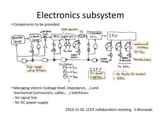
EVLA Converters RF/IF Signal Flow 74 MHz 327 MHz 4/P BAND CONVERTER (L-BAND IF) L-Band C-Band S-Band L/S/C CONVERTER T304 DOWN CONVERTERS X-BAND IF SWITCHES IF A,B,C,D SWITCHES Ku-Band K-Band Ka-Band Q-Band UX CONVERTER EVLA LO-IF CDR • May 17, 2004
System Specifications • System Phase Stability spec 200fs/min over 30 min • Converter spec is 1/3 of this spec • Not yet measured • Have not determined exactly how much will be allocated to each converter EVLA LO-IF CDR • May 17, 2004
T3014/P Converter EVLA LO-IF CDR • May 17, 2004
T301 4/P Converter Design Notes • 2-wide module in LO/IF Rack • Internal Solar Attenuators • Simultaneous 74 MHz & P-band observing • Bandwidth can be changed at a later time by changing filters. • LCP/RCP transfer switches (added 3-2004) to allow simultaneous 4/P and L band observing EVLA LO-IF CDR • May 17, 2004
T301 4/P ConverterBlock Diagram EVLA LO-IF CDR • May 17, 2004
T301 4/P-Band ConverterSpecs • Input Frequencies: 74 MHz (73-75 MHz) P-Band (308-348 MHz) • Bandwidths: 2 MHz (74 MHz) Narrow Band 40 MHz (P-band) • Input Power: -35 dBm/BW • P1dB of Converter: +12 dBm • Headroom: ~74 dB EVLA LO-IF CDR • May 17, 2004
T301 4/P-Band ConverterSpecs • LO: 1024 MHz @ +3dBm • IF Frequency: 1097-1099 MHz Narrow Band • IF Output Power: -45 dBm/BW (To be compatible with L-Band Converter input) • IF flatness: <1 dB/2 MHz • IF-IF Isolation: >65 dB EVLA LO-IF CDR • May 17, 2004
T301 4/P-Band ConverterSpecs IF distribution was recently changed to allow simultaneous 4/P and L–band observing, and to reduce the number of system switches by: • Adding L/S/C or 4/P selector switches to the T302 L/S/C Converter (completed) • Adding RCP/LCP normal/reverse transfer switches to the T301 4/P converter (not yet completed – preventing full T301 testing) EVLA LO-IF CDR • May 17, 2004
T302L/S/C Converter EVLA LO-IF CDR • May 17, 2004
T302 L/S/C Converter Design Notes • 2-wide module in LO/IF Rack • System band switches selects L, S or C band • Internal Solar Attenuators • Internal switches selects L/S/C or 4/P band to allow simultaneous 4/P and L-band observing EVLA LO-IF CDR • May 17, 2004
T302 L/S/C ConverterBlock Diagram EVLA LO-IF CDR • May 17, 2004
T302 L/S/C ConverterRF Input Specs Parameter Specification Measured Frequency range 1–8 GHz Input power level -50 dBm 1dB compression +10 dBm Headroom (-50dBm in) 60dB Headroom (-45dBm in) Input VSWR 1.35:1max 1–8 GHz -45 dBm +3 dBm 53 dB 48 dB 1.08-1.12 EVLA LO-IF CDR • May 17, 2004
T302 L/S/C ConverterLO Specs Parameter Specification Measured LO frequency range 12–20 GHz LO input power level +3dBm LO 2nd harmonic <–40 dBc LO spurious levels <–70 dBc (L301) See note (L301) . NOTE: +17dBm LO mixer injection achieved with LO input power >0dBm. EVLA LO-IF CDR • May 17, 2004
T302 L/S/C ConverterIF Specs Parameter Specification Measured IF frequency range 8–12 GHz IF output power >–50 dBm Conversion Gain not specified Image rejection –30 dBc Overall flatness 1.5dB/2 GHz Passband ripple .2dB/2MHz 8-12 GHz -38 dBm 12-13 dB . ~1.2 dB ~.2dB EVLA LO-IF CDR • May 17, 2004
T302 L/S/C ConverterIF Output Overall flatness & ripple RF: 3.1–4.1 GHz LO: 13.0 GHz Spec: <1.5dB/2 GHz Meas: ~1.2dB/2 GHz 2 GHz sweep not shown Spec: 0.2dB/2 MHz Meas: ~0.2dB/2 MHz SWR 1.08–1.14 (25-29dB reflected) SWR: 0.1/div IF Response 2dB/div EVLA LO-IF CDR • May 17, 2004
T302 L/S/C ConverterIF Output Overall flatness & ripple Miteq Mixer Does not meet spec RF: 3.1–4.1 GHz LO: 13.0 GHz Spec: <1.5dB/2 GHz Meas: ~7dB/2 GHz ~3.5dB/1 GHz 1 GHz Sweep shown SWR: 0.1/div IF Response: 2dB/div EVLA LO-IF CDR • May 17, 2004
T303 UX Converter(Coaxial Version) EVLA LO-IF CDR • May 17, 2004
T303 UX Converter(MMIC Version) Norden Millimeter Prototype #1 EVLA LO-IF CDR • May 17, 2004
T303 UX ConverterDesign Notes • Located in feed cone – custom enclosure • Contains receiver band switches • MIB interface via M301 wire & fiber optics • Powered from front end power supplies • Coaxial & MMIC versions being tested simultaneously EVLA LO-IF CDR • May 17, 2004
T303 UX ConverterBlock Diagram EVLA LO-IF CDR • May 17, 2004
T303 UX ConverterSpecs • RF input frequency: 8 –18 GHz 8–12 GHz Portion: X-band direct IF 12–18 GHz portion: converted to X-band IF • LO input frequency: 12–14 GHz Doubled internally to 24–28 GHz (Only 24–26 GHz portion used) EVLA LO-IF CDR • May 17, 2004
T303 UX ConverterRF Input Specs Parameter Specification Measured Input power level -53dBm/GHz 1dB compression (X/Ku paths) Headroom (X-direct) 38 dB Headroom (Ku path) 25 dB Input VSWR 1.35:1max Input Noise Figure 5.2 dB max -47 dBm† +2/-4 49 dB† 43 dB† 1.08-1.18 Not meas EVLA LO-IF CDR • May 17, 2004
T303 UX ConverterLO Specs Parameter Specification Measured LO input frequency 12–14 GHz LO input power level +10 dBm LO doubled frequency 24–28 GHz LO 2nd harmonic <–40 dBc LO spurious levels <–70 dBc (L301) +10dBm 24-27.5† . . † Power reduced –3dB 27.5–28.0 GHz EVLA LO-IF CDR • May 17, 2004
T303 UX ConverterIF Specs Parameter Specification Measured IF frequency range 8–12 GHz IF output power >–48 dBm Conversion Gain not specified Image rejection –30 dBc Overall flatness 2dB/2 GHz Passband ripple .2dB/2MHz 8-12 GHz -43 dBm 12-13 dB . 1.5dB .2dB max EVLA LO-IF CDR • May 17, 2004
T303X-Direct Path Overall flatness & ripple MMIC Version X-Direct Path RF: 8–12 GHz LO: Not used Spec: 2dB/2 GHz Meas: ~1.5dB/4 GHz 4 GHz sweep shown SWR 1.08–1.12 SWR 0.1/div IF OUT 2dB/div EVLA LO-IF CDR • May 17, 2004
T303Ku Conversion Path Overall flatness & ripple MMIC Version Ku-converted Path RF: 12–18 GHz LO: 12.0 GHz Spec: 2dB/2 GHz Meas: 3.8dB/6 GHz 6 GHz sweep shown Meas. SWR 1.08–1.12 SWR 0.1/div IF OUT 2dB/div EVLA LO-IF CDR • May 17, 2004
T303Compression/IMD Ku-converted Path 12–18 GHz @ +5dBm LO: 12.0 GHz Spec: 32dB headroom from P1dB -40dBm+32=–8dBm Meas P1dB= –2dBm Spec: IMD <<30dB LO spurs <-60dBc IMD product –65dBc SWR 0.1/div IF OUT 10dB/div EVLA LO-IF CDR • May 17, 2004
T303 UX ConverterIF Output When things go wrong. . . SWR 0.1/div IF OUT 10dB/div EVLA LO-IF CDR • May 17, 2004
M301 ConverterInterface Module • One MIB services all three converters and controls all system switches • M301 to reduce MIB RFI in converters • Uses MIB SPI bus for all monitor/control • Fiber Optics used for feed cone SPI lines EVLA LO-IF CDR • May 17, 2004
M301 Converter Interface Block Diagram EVLA LO-IF CDR • May 17, 2004