Download
1 / 24
240 likes | 257 Vues
Detailed analysis, optimization, and results of the mechanical model for coil assembly work at CERN, including stress profiles and failure criteria. This summary covers the assembly procedure, sensitivity study, and the 3D mechanical model setup for force transfer analysis.

E N D
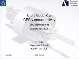
Short Model CoilCERN status activity SMC working group January-25th, 2008 F. Regis Supervisor P.Fessia CERN - AT-MCS SMC - F.Regis
Summary • 2D mechanical Resume of the activity • 3D mechanical Optimization of the routine to transfer forces and first results • Remarks and conclusions SMC - F.Regis
2D Mechanical model • Magnet assembly: Plane42 (4nodes element) • Contact elements: Conta171, Targe169 • 1st step: assembly (interference between vkey and yoke) • 2nd step: cool down at 4.2K • 3rd step: powering @ [0.25-0.5-0.75-0.9-1.2] of Iss Start–up parameters • Analysis procedure • ix = [100, 200, 400, 600, 800, 1000] • Check for σmax on coil to keep it lower then 150MPa @ Iss • Check for Stress profile on pole – coil pack to assure compression @ Iss • Check for Stress distribution on assembly components (Von Mises criterion) • The Yoke shows brittle behavior at cryo temperature so the failure criterion adopted is Rankine’s (maximum primary stress). It is assumed without any defects. SMC - F.Regis
Results – σmax,VM SMC - F.Regis
Results – ix = 400mm Assembly Cool Down Iss σeqv,VM (MPa) σx (MPa) SMC - F.Regis
Failure criteria & displacements Yoke: Magnetil steel σ1,max = 251 MPa < 480 MPa = σx,lim/s Where: s=1.5 Safety Factor σx,lim=720 (7K) Shell: Al 2014-T651 σVMeqv,max = 163 MPa < 363 MPa = σx,lim/s Where: s=1.5 Safety Factor σx,lim=545 (4.2K) Pad-X Pad-Y clearance ePx-Py= ~4mm – ΔxCD = 3.75mm Where ΔxCD = 0.251mm is from ux,px(p2)- ux,py(p3) ux,yoke(p2) = -0.12mm @ CD SMC - F.Regis
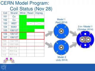
Sensitivity study Analysis Criteria • The stress distribution σx on the island-coil side must be around 20 MPa @ Iss • The failure criteria for the yoke and shell must be satisfied • The σxmax on the coil pack must be lower then 150 MPa • Iss computed for each configuration of wyoke • It can be shown that • To get the required pre-σ on the coil pack, the bigger the yoke the smaller the outer tube radius, up to a limit where the shell thickness seems to be ineffective. • tshell = 17mm & wyoke = 70mm could be chosen as minimum reference value. This configuration respects all the design constraints, it gives a good margin on Bmax and allows reduced dimensions of the assembly SMC - F.Regis
Assembly analysis • With the first model the assembly procedure was simulated by setting contact interference between lateral key and yoke • The aim of this part of the work has been the implementation of the whole assembly procedure • The yoke key has been introduced into the model, following the assembly guideline of SD01 (Helene’s thesis: Mise en oeuvre et test de SD) • Birth & Death option has been exploited to simulate keys insertion after bladders pressurization • Frictionless model Yoke key and bladder εθ Pad keys and bladders SMC - F.Regis
Assembly: trial runs SD01 assembly procedure as it comes from the measurements SMC - F.Regis
2D – Assembly procedure • Analysis procedure • All the keys are inactive • Pressurize bladder on yoke • “Insert” yoke key, then remove bladders pressure. The aim is to get pre-σ in the yoke-shell assembly to assure adequate contact between the two components. • Pressurize bladders for horizontal and vertical keys • “Insert” keys. The dimension is such that the yoke key becomes “loose” • Pressurize bladders in between pad-X and yoke for target pre-σ • “Insert” final key’s shim • The interference of the yoke key is about 110 µm to get εθ~200 µε • The yoke key becomes “loose” with a lateral interference of 200 µm • The target lateral interference is 400 µm • No interference for the horizontal key SMC - F.Regis
3D model • The 3D magnetic model with MSP formulation will be used to prepare input forces for mechanical calculations • Due to the mesh procedure (vsweep command) not only the mesh and nodes must be the same between magnetic and mechanical model, but the volume numbers too. • Re-arrangement of the magnetic model has been done to assure complete matching with the mechanical one, at least up to the mesh of the coil pack. BUT the mesh used for magnetic computation is not effective for mechanical purposes • The need for different coil mesh prevent from using automatic force transfer command LDREAD • An optimized routine has been set-up to transfer e.m. forces from magnetic model to mechanical one, based on nodal coordinates and numbers • The routine takes about two hours for complete transfer if based on nodal coordinates (first run, new geometry or mesh). It takes about 2minutes for the second run on SMC - F.Regis
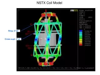
3D model • Constraints have been set to respect mechanical symmetry • First computations have been performed leaving the coilpack completely free to move on the outer c.p. edge SMC - F.Regis
3D model MAG MEC • 3 Divisions for bare cable width to avoid numerical imprecision between insulation and bare cable SMC - F.Regis
3D model Ux Cool Down 13.8kA SMC - F.Regis
3D model Uy Cool Down 13.8kA SMC - F.Regis
3D model Uz Cool Down 13.8kA SMC - F.Regis
3D model σx Cool Down 13.8kA SMC - F.Regis
3D model σx 13.8kA – 3D Iss – 2D SMC - F.Regis
3D model σy Cool Down 13.8kA SMC - F.Regis
3D model σz Cool Down 13.8kA SMC - F.Regis
3D model 1st pack Cool Down 13.8kA SMC - F.Regis
3D model 1st pack Cool Down 13.8kA • The higher displacement along vertical direction is explained by the effect of Fmag on the coil pack, crating a torque on the first two packs SMC - F.Regis
3D Solid model SMC - F.Regis
Remarks & Conclusions • The assembly procedure has been set up (2D frictionless model) • This is only one possible scenario, the assembly procedure could be different, but the technique of simulating that has been acquired • The 3D model is under study • Optimization work on coil mesh has been done • A routine to transfer forces has been built in ANSYS • First results shows consistent results to physical behavior of the coilpack; analysis of the effect of the different thermal contraction coefficient will be performed • Some calculations still to be done, but we will start immediately the set up of the complete model. SMC - F.Regis