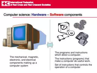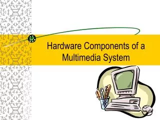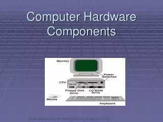
Hardware Components
Lesson 3 0x003 011. Hardware Components. Modified and presented by : Mohamed Zaki . Topics. Simple Computer Architecture CPU Architecture CPU Registers Executing instruction Instruction set types Memory Devices Bus Systems Input / Output Architecture.

Hardware Components
E N D
Presentation Transcript
Lesson 3 0x003011 Hardware Components Modified and presented by : Mohamed Zaki
Topics • Simple Computer Architecture • CPU Architecture • CPU Registers • Executing instruction • Instruction set types • Memory Devices • Bus Systems • Input / Output Architecture
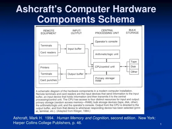
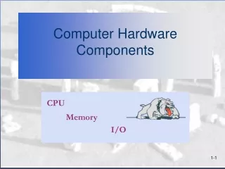
COMPUTER ARCHITECTURE Von Neumann Architecture CPU/ Processor Main Memory Address Bus Data Bus Control Bus Input & Output Devices
Examples of CPUs • Based on the manufacturer: • Intel: • Celeron • Pentium I. • Pentium MMX. ( Multimedia Extension) • Pentium II. • PentiumIII. • Pentium 4. • Centrino. ( Mobile Technology) • Core 2 DUO • Dual core • Quad core • Core i series (Laptop, Desktop, and Mobile Device Processors) • Xeon (Server and Workstation Processors) • AMD. • ARM • Dual Core A4,A5, A6 • ARM Cortex-A9 MPCore (for iPad & iPhone and others)
CPU Architecture CPU : Central Processing Unit. Also called Processor • CPU: • is the part of a computer in which arithmetic and logical operations are performed and instructions are decoded then executed. • The clock: • It is a circuit for generating pulses that enable computer components to work in an ordered manner .
CPU Architecture CPU : Central Processing Unit. Also called Processor • CPU Components: • ALU ( Arithmetic and Logic Unit) • Is the unit where all Arithmetic and logic operation are performed • CU (Control Unit) • Is the unit which controls communication and co-ordination between input/output devices. • Registers: • Are high speed & small in size temporary memory storage areas used during data manipulation ( calculation , comparison , etc..)
CPU Architecture Main Memory / RAM / Primary Memory ALU Control Unit GENERAL PURPOS REGISTER CIR MAR Program Counter Register MBR Bus : set of wires
CPU Registers • General purpose registers: • are used to hold data before and after it is manipulated. Also used for many operation such addition, subtraction multiplication and logic operations • Special Purpose Registers: • Program counter PC: it is loaded with the address in memory of the first instruction location of a program. After fetching, it is increased to point to the next location. • Memory Buffer register MBR: all data and instructions pass in and out from the main storage through MBR. • Current instruction register CIR: an instruction to be performed will be taken from the main storage via the MBR and placed in register IR. • Memory address register MAR : prior to each transfer between the MBR and main storage , the exact source or destination of data in the main storage must be specified by MAR.
Copy PC contents into MAR & Initiate a memory read Increment the PC Copy the instruction Which is in the MBR into CIR Decode the CIR Execute the instruction Executing a Software Program The chart shows the steps that the CPU uses to execute a software
Instruction set types Each CPU has a set of instructions • Arithmetic and Logic inst. Set: Such as addition, subtraction, multiplication, Increment, decrement, and logical operations, Such as add, sub,mul. • I/O instructions: To transfer data between peripherals and memory, or between peripherals and accumulator, Such as mov • Processor reference instructions: To stop the microprocessor activities. Such as halt. • Fetch (Load) and store instruction: To transfer the data between accumulator and memory, Such as load • Memory reference instructions: To access the memory during their execution, it is both Load + store instructions. • Transfer of control, or branch instruction: (Executing a Program) To change the program sequence. Such as jmp
Memory Devices • Any memory is constructed from a collection of memory cells, each having unique address. • Each cell contains a combination of binary data(0 or 1). • Types of Memory: • RAM. • ROM. • Cache Memory.
Random Access Memory (RAM) • It also called Main or Primary Memory. • Programs & Data are stored there before processing . • The larger amount ofRAM, the quicker programs will run. • More than one type of RAMs are used in modern PCs, like DRAM(Dynamic RAM) and SDRAM(Synchronous DRAM) • The data will be lost if the power is cut(Volatile Memory).
Read Only Memory (ROM) • It holds the firmware program (BIOS). • It starts the POST “ power on self test” program • It contains auto-startup program that will load the necessary OS programs in RAM. • The information remains in the ROM when the computer turned off. ( Nonvolatile Memory)
Cache Memory • Is a small memory, located close to the processor? • Some processors are built with internal cache memory. • It has much shorter access time than the RAM. Therefore, it is used to hold instructions and data that has recently been accessed. • There are two types of cache memory: L1 and L2. • L1 ( Level 1) internal cache, built in with in the CPU. • L2 ( Level 2) external cache, built in with in the Motherboard, L2 is lager than L1.( A+ Book p 131)
CPU, RAM, and Cache Diagram CPU • Write through cache. • Write back cache. Cache RAM
Hard Disk is a data storage device used for storing and retrieving digital information using rapidly rotating discs (platters) coated with magnetic material. • A magnetic heads arranged on a moving arm to read and write data to the surfaces.
Bit Value is 1 Bit Value is 0 0 0 1 0 1 1 1 0 Disk Organization Magnetic polarity determines the bit value (1,0) Sector Track The Format Commandis used to create Tracks and Sectors
Other Storage Devices Flash Memory DVD Disks Magnetic Tapes
Storage Device Hierarchy Bytes Registers 1 nsec M Bytes Cache 10 nsec Speed Size G Bytes Main Memory 100 nsec G Bytes Flash Memory msec G – T Bytes Hard Disks msec T Bytes Magnetic Tapes sec -min Hard Disk and Tapes have mechanical movements Others do not have and called Solid Sate Devices (SSD)
Bus Systems (Connecting them together ) • Is a collection of parallel electrical lines which connect the computer components. • The buses used to transfer: • Data signals. • Address signals. • Control signals. • Power.
Bus Systems Address Bus • The address bus is the set of wires carrying the addressing information used to describe the memory location, which the data is being sent or retrieved. • The size of the address bus indicates the maximum amount of RAM that a chip can address. Size of memory that can be addressed= 2L Were L = No. of Lines in address bus ( Size of address bus)
Bus Systems Address Bus
Bus Systems Address Bus Examples: 1): how many addresses can be built by 3 digits (3 lines): 2n = 23 = 8 address bus locations from ( 000 to 111 ) 2): how many addresses can be built by 5 digits (3 lines): 2n = 25 = 32 address bus locations from ( 00000 to 11111 ) 3) : how many address bus we need for a memory with 1kb size. 2x= 1024 ….. Then x = 10
Input / Output Architecture • The computer has the ability to send and receive data to and from other devices. • We can transfer data in parallel and serial lines. • When the CPU wishes to send data to a particular I/O devices it places a unique identity code ( address ) onto the address line. • Only the device that recognizes that code will respond to the command that is placed on the control line.